Insulation resistance tells you whether a transformer is dry and clean, but it does not tell the whole story about its dielectric system. The power factor test, also called the tan delta or dissipation factor test, measures how much energy is lost in the insulation when an AC voltage is applied to it. It is one of the most useful tests in predictive maintenance of power and distribution transformers, because it detects moisture, contamination, ageing of paper and oil, and bushing defects long before they turn into a failure. This guide explains what the test measures, how it is performed, what the CH, CL and CHL capacitances mean and how to interpret the results without falling into common mistakes.
What insulation power factor measures
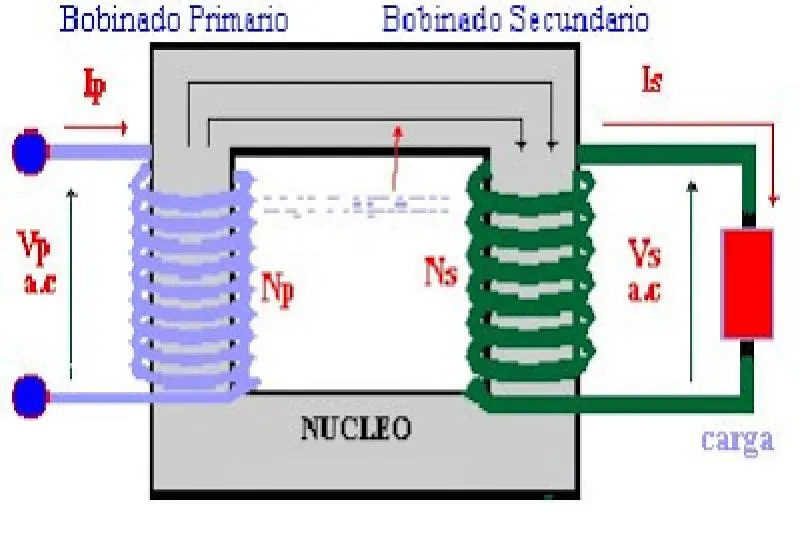
Ideal insulation behaves like a perfect capacitor: the current that flows when AC voltage is applied leads the voltage by 90° and there are no losses. Real insulation also carries a small resistive current, in phase with the voltage, which represents conduction and polarization losses. Two parameters describe this relationship:
- Power factor (PF): the cosine of the angle between voltage and total current; it is the resistive current divided by the total current.
- Dissipation factor or tan delta (tan δ): the resistive current divided by the capacitive current. δ is the complement of the phase angle.
At the low values found in healthy insulation, the two are practically equal, so in the field they are used almost interchangeably. What matters is that the result is a ratio, independent of the size of the equipment: it lets you compare different transformers and, above all, follow the trend of the same transformer over the years. Besides losses, the instrument measures capacitance, which gives information about the geometry of the insulation.
Capacitances of a two-winding transformer
The insulation of a two-winding transformer is modelled as three capacitances:
| Capacitance | Insulation it represents |
|---|---|
| CH | Between the high-voltage winding and ground (tank and core), including the HV bushings |
| CL | Between the low-voltage winding and ground, including the LV bushings |
| CHL | Between the high- and low-voltage windings (barriers, paper and oil between them) |
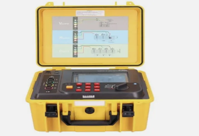
The test set separates each capacitance through its connection modes: GST (grounded specimen test) measures everything going to ground; GST with guard excludes part of the circuit to isolate, for example, CH; and UST (ungrounded specimen test) measures only between two terminals, such as CHL. Three-winding transformers add more capacitances, but the principle is the same.
How the test is performed
- Safety first. The transformer must be de-energized, locked out and tagged out, grounded and discharged, following the plant procedure, NOM-029-STPS and NFPA 70E practices. The test set applies high voltage, so the area must be barricaded.
- Preparation. Cables and bus bars are disconnected from the bushings. Each winding is short-circuited across its terminals (all HV phases together and all LV phases together) and the neutral is disconnected from ground. This removes the effect of winding inductance.
- Bushing cleaning. Dirt and moisture on the porcelain create surface leakage currents that raise the GST result. Clean and dry the surfaces before measuring.
- Test voltage. 10 kV at power frequency is often used, but the voltage must never exceed the rating of the lowest-voltage winding or the limit given by the manufacturer. Always use the same voltage in successive tests so trends are comparable.
- Record conditions. Note oil and winding temperature, ambient temperature and relative humidity. Without this data, interpretation loses much of its value.
Bushing tests
Condenser-type bushings with a test tap are evaluated separately. C1 is the main insulation, between the centre conductor and the tap, and is measured in UST mode; C2 is the insulation between the tap and the grounded flange. C1 values are compared with the nameplate: in addition to power factor, an increase in capacitance can indicate shorted condenser layers. For bushings without a tap there is the hot collar test, which evaluates the upper section of the porcelain.
Temperature correction
The power factor of paper-and-oil insulation increases with temperature. Results are therefore corrected to a reference temperature, usually 20 °C, so they can be compared. Correction tables depend on the type of insulation, its ageing and the guide used, such as IEEE C57.152 or the manufacturer’s own; a generic correction factor can introduce significant errors in aged or wet insulation. Some modern instruments estimate an individual correction for each insulation using measurements at several frequencies. In any case, the most reliable approach is to always test at similar temperatures and avoid testing below freezing or with condensation on the surfaces.
How to interpret the results
There is no single limit value for every transformer. As a frequently cited reference, many new oil-filled power transformers show power factors at 20 °C in the order of 0.5 % or less, but the applicable criterion depends on design, age, insulation type and the edition of the guide being used. Dry-type transformers, for example, have higher typical values. Good interpretation practice includes:
- Compare with the unit’s own history. A sustained increase between tests is more significant than the absolute value.
- Compare between phases and between sister units of the same manufacturer and design.
- Watch the capacitance. A noticeable change in CHL or CH can indicate winding deformation or displacement, for example after a short circuit; it should be confirmed with other tests.
- Analyse which capacitance changed. If only CH rises, the problem may be in the HV bushings or in that winding’s insulation to ground; if everything rises, it points to moisture or general ageing of the oil and paper.
- Voltage tip-up test. Measuring at several voltages helps detect ionization: in healthy insulation the power factor barely changes as voltage increases.
Complementary tests
Power factor is most useful when interpreted together with other tests. Insulation resistance with polarization index confirms moisture or contamination problems; oil dielectric breakdown shows whether the oil needs treatment; and turns ratio and excitation current help rule out winding and core problems. A maintenance programme that combines these measurements lets you decide with data whether a transformer can stay in service, needs drying or oil treatment, or should be scheduled for a major overhaul.
How CreativeIT can help
At CreativeIT Group in Monterrey we carry out transformer testing and other diagnostic electrical services, and we deliver results with their interpretation so you can plan maintenance. If you need to assess the insulation of your transformers or establish a baseline for your trends, contact us at (81) 4777 6921 or info@creativeit.mx.