Before designing a grounding system for a substation, a new plant or a lightning protection system, one figure shapes everything else: soil resistivity. The resistance an electrode or grid will achieve depends directly on how well the surrounding soil conducts, and that value can vary enormously from one site to the next, and even between the surface layer and the soil a few metres down. Designing without measuring it means guessing, and a wrong guess is expensive: oversized grids, extra rods added after construction or, worse, a system that does not meet the required safety values. This guide explains how a soil resistivity survey is carried out with the Wenner method, how to interpret the results and which field mistakes to avoid.
Resistivity and ground resistance are not the same
The two concepts are often confused:
- Soil resistivity (ρ): a property of the ground, expressed in ohm-metres (Ω·m), describing how well a volume of soil conducts current. It depends on soil type, moisture, temperature and dissolved salts.
- Ground resistance (R): a property of an installed electrode or system, expressed in ohms (Ω), which depends on soil resistivity and on the electrode geometry (rod length, grid size, burial depth).
Ground resistance is measured on an existing system to verify it complies; resistivity is measured before construction, in order to design. For testing installed systems, see our ground and lightning protection testing service.
What a resistivity survey is used for
- Substation grounding grid design: IEEE Std 80 uses the soil model to calculate grid resistance and step and touch voltages.
- Grounding design for plants and buildings that must meet the grounding requirements of NOM-001-SEDE.
- Choosing the best location for electrodes, ground wells or line counterpoises.
- Cathodic protection and corrosion studies for buried pipelines, where resistivity is an indicator of soil corrosivity.
The Wenner (four-pin) method
This is the most widely used method and is described in IEEE Std 81. Four electrodes are driven in a straight line, with equal spacing a between them and at a depth b. The instrument injects current between the two outer electrodes and measures the potential difference between the two inner ones. The ratio of that voltage to the current is the resistance R displayed by the tester.
When the electrode depth is small compared with their spacing, the apparent resistivity is calculated with the simplified formula:
ρ = 2 · π · a · R
where a is in metres and R in ohms. If the electrodes are driven to a depth that is not negligible relative to the spacing, IEEE 81 gives the full formula, which includes the depth b. Many four-pole earth testers perform this calculation automatically once the spacing is entered.
Why measurements are taken at several spacings
As the electrode spacing increases, the current penetrates deeper into the ground. As a practical approximation, the apparent resistivity measured with spacing a represents the soil down to a depth of the order of a. That is why a survey is not a single reading: the measurement is repeated at a series of increasing spacings (for example 1, 2, 4, 8, 16 and 32 m, depending on the size of the system to be designed) to build a profile of resistivity versus depth.
The Schlumberger variant
In the Schlumberger arrangement the potential electrodes stay near the centre and only the current electrodes are moved. This reduces the number of moves at large spacings and can be faster on extensive sites; in exchange, the measured signal is smaller and the calculation is different. Both methods are valid when applied correctly.
How to carry out the field measurement
- Several traverses: measure in at least two directions, ideally perpendicular, and in different areas of the site. If the results differ widely, the soil is not homogeneous and the survey should be extended.
- Stay away from buried metal: pipes, cables, metal fences and existing grids offer a low-resistance path for the current and distort the readings. Avoid running the traverse parallel to them.
- Good electrode contact: in very dry or rocky soil the contact resistance of the pins can be high; wetting the ground around the pins improves contact without significantly affecting the measurement of the soil volume.
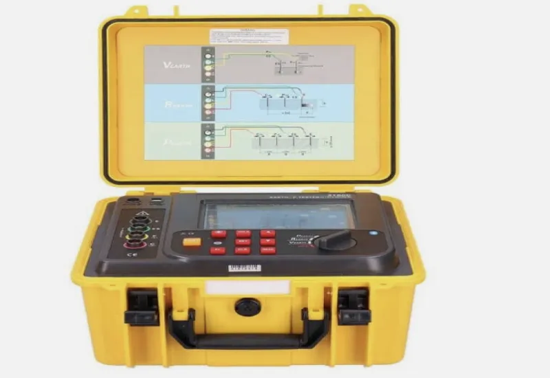
- Use a suitable instrument: a four-pole earth tester that works with alternating current at a frequency different from the mains frequency, to reject stray currents and induced voltages.
- Record the conditions: date, recent weather, apparent soil moisture, coordinates and orientation of each traverse.
How to interpret the results
The result is presented as a graph of apparent resistivity versus spacing:
| Curve shape | Interpretation |
|---|---|
| Roughly flat | Reasonably homogeneous soil; a uniform model can be used |
| Falling as spacing increases | A more resistive surface layer over a more conductive lower layer; long or deep rods are usually effective |
| Rising as spacing increases | A conductive surface layer over rock or more resistive material; it is better to extend the grid in area rather than in depth |
For grid design, the data are fitted to a two-layer model (upper-layer resistivity, its thickness and lower-layer resistivity), usually with specialised software. A well-fitted model lets you calculate the expected grid resistance and the step and touch voltages before construction.
Moisture and season matter
Soil resistivity depends strongly on its water content and dissolved salts. A measurement taken after several days of rain can give much lower values than one taken in the middle of the dry season. A good survey states the conditions under which it was measured, and the design should consider unfavourable conditions, not the most favourable ones. For the same reason, the resistance of a completed grounding system should be checked periodically.
What the report should include
- Location and sketch of the traverses measured.
- Method used, instrument, serial number and calibration status.
- Table of spacings, measured resistances and calculated resistivities.
- Graphs for each traverse and, if requested, the fitted soil model.
- Ground and weather conditions during the measurement.
How CreativeIT can help
At CreativeIT Group in Monterrey we carry out soil resistivity surveys and resistivity and ground resistance services for the design and verification of grounding systems. If your team prefers to take the measurements, we also offer soil resistivity tester rental. Contact us on (81) 4777 6921 or at info@creativeit.mx to plan your survey.