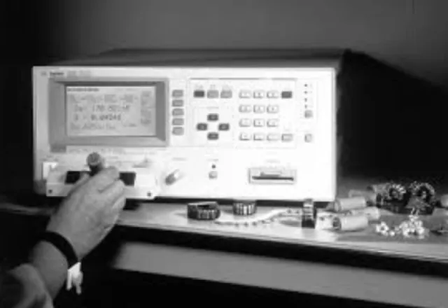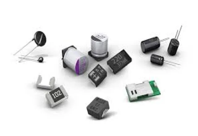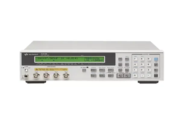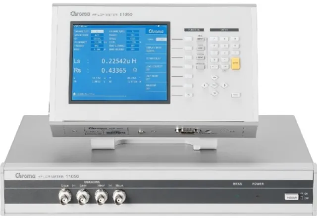
A capacitor marked 10 µF can read 9.8 µF on one LCR meter and 7 µF on another, and neither instrument may be faulty. The impedance of a real component depends on frequency, signal level, DC bias, temperature and how it is connected to the instrument. An LCR meter does not measure “capacitance” in the abstract: it measures impedance under specific conditions and translates it into an electrical model. If those conditions are wrong, the number on the display can be precise and still be useless. This guide explains how an LCR meter works, which parameters to set and which mistakes to avoid in incoming inspection, repair and design validation.
What an LCR meter actually measures
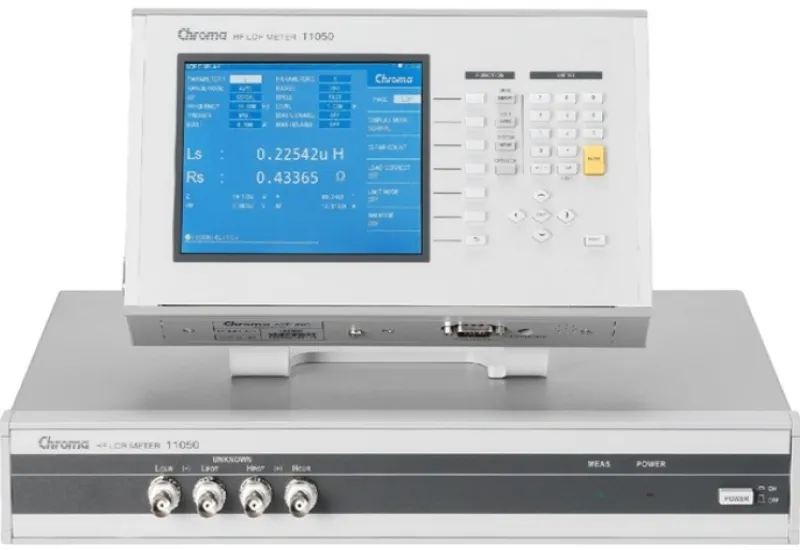
The instrument applies an AC signal of known frequency and amplitude, measures the voltage across the component and the current through it, and calculates the complex impedance: its magnitude |Z| and phase angle θ. From these two values it derives the parameters the user selects:
- L, C and R: inductance, capacitance and resistance according to the chosen equivalent model.
- D (dissipation factor): for capacitors it equals the tangent of the loss angle, tan δ. A higher value means more loss.
- Q (quality factor): the inverse of D, D = 1/Q. It is used mainly for inductors.
- ESR: the equivalent series resistance, essential for evaluating electrolytic capacitors in switch-mode power supplies.
Series or parallel model
No component is ideal. A capacitor has losses that can be represented as a resistance in series or a resistance in parallel, and the calculated value of C changes with the model. Both readings are mathematically correct; the question is which one better represents the component under those conditions. A rule of thumb widely used in manufacturers’ literature is:
| Component impedance | Recommended model | Examples |
|---|---|---|
| Low (roughly below 100 Ω) | Series (Cs, Ls) | Large capacitors, small inductors |
| High (roughly above 10 kΩ) | Parallel (Cp, Lp) | Small capacitors, large inductors |
| In between | As recommended by the component manufacturer | Case by case |
Remember that a capacitor’s impedance falls as frequency rises while an inductor’s rises, so the same component can move from one model to the other if the test frequency changes. Most importantly, measure with the same model the component datasheet specifies, so the comparison is meaningful.
Test frequency and signal level
Frequency
Datasheets specify the nominal value at a given frequency. As common practice, aluminum electrolytic capacitors are specified at 100 or 120 Hz, many ceramic capacitors at 1 kHz and very small-value ceramics at 1 MHz. Power inductors are specified at whatever frequency their manufacturer states. Measuring at another frequency is not wrong, but the result is not comparable with the nominal value. In addition, close to the component’s self-resonant frequency, L or C readings lose their physical meaning.
Signal level and DC bias
Some components change value with signal amplitude. Class 2 ceramic capacitors such as X7R or X5R vary with the applied AC voltage and lose significant capacitance under DC bias voltage. Ferrite-core inductors change with current and approach saturation as it increases. Set the level stated in the datasheet and, if the component will operate with DC, use the instrument’s bias function or an external fixture, within the limits the equipment allows.
Connection: the most underestimated error
With very low impedances, the resistance and inductance of the leads add to the measurement. With very high impedances, stray capacitance between the probes and the proximity of a hand affect the result. That is why there are several configurations:
- Two-terminal: simple, suitable only for mid-range impedances.
- Three-terminal (guarded): reduces the effect of stray capacitance at high impedances.
- Four-terminal (Kelvin): separates current and voltage paths and removes the effect of lead resistance at low impedances.
- Four-terminal pair: used in precision instruments with coaxial cables; it also reduces inductive effects and extends the useful range.
Use the right test fixtures for each package, whether axial, radial or surface-mount, and keep the leads short and in the same position throughout the measurement.
Open and short compensation
Compensation corrects for the effects of the cabling and the fixture. Open correction is done with the probes open and removes stray admittance; short correction is done with the probes shorted and removes residual impedance. It must be done at the end of the fixture, at the test frequencies that will be used, and repeated whenever the fixture, the cables or the setup change. Many instruments also allow a correction with a known load for higher accuracy, and ask for the test cable length to be entered.
How to read LCR meter accuracy
The “basic accuracy” on the front page of a datasheet is met only under optimal conditions: a mid-range impedance, certain frequencies, a suitable signal level and slow measurement time. Outside those conditions accuracy gets worse, sometimes considerably. Manufacturers publish accuracy tables or charts as a function of impedance and frequency; check the one that matches your real measurement. For components with very low D or very high Q, phase error weighs heavily and can limit ESR or Q accuracy even when C or L accuracy is good.
Common mistakes
- Not discharging capacitors: a charged capacitor can damage the instrument inputs and is a hazard for the technician. Always discharge it before connecting.
- Measuring in circuit: parallel components distort the reading; for reliable results, measure the component off the board.
- Ignoring temperature: many dielectrics and magnetic cores change with temperature, even from the heat of a hand.
- Skipping compensation: the most common cause of disagreement between two instruments that are in fact working correctly.
LCR meter or impedance analyzer
An LCR meter measures at spot frequencies and is ideal for incoming inspection, quality control and repair. An impedance analyzer sweeps a wide frequency range and shows how impedance changes, which makes it possible to see self-resonance, characterize materials or model components for design. To choose, first define which components you will measure, at what frequencies and to what tolerance, and whether you need DC bias, interfaces for test automation or specific fixtures. If the need is occasional, for example a validation or an audit, renting the equipment is usually more convenient than buying it.
How CreativeIT can help
CreativeIT Group, in Monterrey, works with LCR meters and impedance measurement products. We sell equipment such as the HP 4263B LCR meter, offer Agilent 4285A precision LCR meter rental and provide capacitor, inductor and resistor characterization services in our laboratory. Contact us at +52 (81) 4777 6921 or info@creativeit.mx and tell us which components you need to measure.