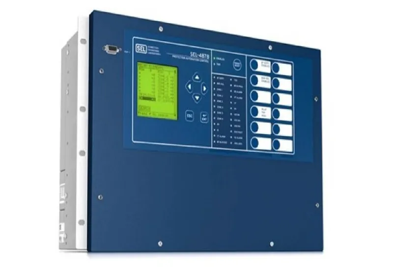
A protection relay can go years without operating, and when a fault finally happens it has a fraction of a second to do its job. If its settings do not match the coordination study, if a current input is damaged or if the trip circuit is open, the result can be a breaker that does not open, a fault that spreads upstream or a full plant shutdown from a trip that should never have happened. The worrying part is that none of this shows during normal operation: the relay looks healthy until the day it is needed. Periodic testing is the only way to know the protection actually works. This guide explains what is checked in a relay, how a secondary injection test is carried out and how to interpret the results.
Why test a relay that has “never failed”
A relay that has not operated is not necessarily in good condition; usually it just means there has been no fault in its zone. Typical problems that a test uncovers include:
- Wrong settings: loaded values that do not match the current study, changes made during commissioning and never documented, or the wrong settings group active.
- Damaged analog inputs: internal current or voltage transformers that measure incorrectly after an overload or a transient.
- Output contacts and digital inputs: contacts that do not close, inputs that do not detect breaker status, or logic that does not run as expected.
- Trip circuit: loose wiring, blown fuses, a damaged trip coil or a problem with the DC control supply.
- Electromechanical relays: mechanical wear, dirt, pitted contacts or drift in the induction disc calibration.
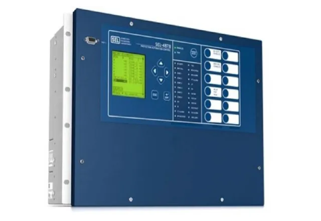
Numerical (microprocessor) relays have self-diagnostics, but these mainly check their internal hardware. They do not confirm that the settings are correct or that the trip reaches the breaker.
Standards and references
- IEEE C37.2: defines the ANSI device numbers, such as 50 (instantaneous overcurrent), 51 (time overcurrent), 87 (differential), 27 and 59 (under- and overvoltage), 81 (frequency) and 86 (lockout relay).
- IEEE C37.112 and IEC 60255-151: define the inverse-time curve equations used by overcurrent relays.
- IEC 60255 series: requirements and tests for measuring relays and protection equipment.
- ANSI/NETA ATS and MTS: acceptance and maintenance testing specifications, widely used as a guide to what should be tested.
- NFPA 70B: electrical equipment maintenance, with intervals based on equipment condition and criticality.
- NFPA 70E and NOM-029-STPS: safety during maintenance work on electrical installations.
The right test interval depends on the relay type, the criticality of the load and the equipment history. Check the current edition of the standard your company follows and the manufacturer’s recommendations.
Secondary injection and primary injection
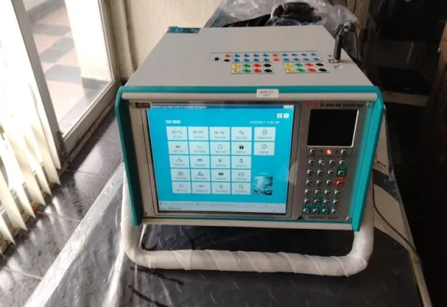
The most common test is secondary injection: the signals coming from the current transformers (CTs) and voltage transformers (VTs) are disconnected, and a relay test set injects controlled currents and voltages directly into the relay inputs. Three-phase or six-phase test sets can simulate balanced and unbalanced faults and test functions such as differential protection, which needs currents on both sides of the protected equipment.
Primary injection applies current on the primary side of the CTs, so it tests the whole chain: CTs, wiring, relay and trip. It requires high-current equipment and more preparation, and is usually reserved for commissioning or for cases where a problem with the CTs or their wiring is suspected.
What is tested, function by function
Time overcurrent (51) and instantaneous (50)
- Pickup: current is raised slowly until the relay picks up, and the value is compared with the setting.
- Operating time: several multiples of pickup are applied, for example 2, 5 and 10 times, and the time to trip is measured. Each result is compared with the theoretical time for the set curve and time dial.
- Instantaneous: the pickup value is checked, along with the expected operating time.
- Neutral or ground (50N/51N): the test is repeated on the ground element, which usually has much more sensitive settings.
Differential (87)
On transformers, generators or busbars, the minimum pickup is checked, along with the slope characteristic (the operating current required at different restraint currents) and harmonic restraint, which prevents tripping on transformer energizing (inrush) current and is usually based on the second harmonic. On transformers it is also necessary to confirm that vector group and ratio compensation are configured correctly.
Voltage and frequency (27, 59, 81)
Pickup values, time delays and, where applicable, undervoltage blocking that prevents false operations are verified.
Logic, inputs and outputs
On numerical relays, the digital inputs (breaker position, external trips), the output contacts and the programmed logic schemes are tested: reclosing, breaker failure (50BF), interlocks and signals to the SCADA system. Finally, the event records are downloaded to confirm the relay logged each test correctly.
Precautions before injecting
- Isolate the trip: open the test blocks or test switches on the trip outputs, or coordinate with operations, so an in-service breaker is not opened by accident.
- Never open a loaded CT secondary: if the primary circuit is energized, the secondary must be shorted before the relay is disconnected. A CT with an open secondary can develop dangerous voltages and be damaged.
- Have the settings and the study at hand: the test compares the relay with what it should have, not only with what it has.
- Record the original state: back up the settings file before any change and note the position of every test switch so they are returned the same way.
How to interpret the results
Each measured value is compared with the setting and with the tolerance published by the relay manufacturer, for both pickup and timing. A deviation within tolerance is normal; a large deviation, or one that is inconsistent between phases, points to an input, settings or, on electromechanical relays, calibration problem. In the field, many of the most common errors are not hardware faults but configuration issues: a time dial different from the study, a CT ratio entered incorrectly in the relay, or an enabled function nobody remembers turning on.
The report should include the settings tested, the theoretical and measured values, the test set used and its calibration status, and the functional trip test to the breaker. That last item is the most important: a perfect relay is useless if its trip command never reaches the coil.
Frequently asked questions
Should a relay be tested after its settings are changed?
Yes. Any change to settings, firmware or wiring should be followed by a check of the affected functions and of the trip.
Does testing require de-energizing the substation?
Not always. With test blocks and good planning, many secondary injection tests can be done with the primary equipment in service, although the functional trip test to the breaker usually needs a maintenance window.
How CreativeIT can help
CreativeIT Group, in Monterrey, provides substation relay measurement and testing services as part of our electrical services, which also include transformer testing. If your team prefers to run the tests itself, we offer six-phase relay test set rental. Contact us at +52 (81) 4777 6921 or info@creativeit.mx to plan the testing of your protection system.