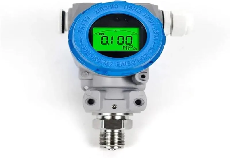
A pressure transmitter that drifts a few tenths of a percent may seem like a minor detail, but in a control loop that error becomes a misread level, an incorrect dosing rate or a safety trip that does not happen when it should. HART transmitters make the job much easier because the instrument can be queried and adjusted digitally, but they also cause a very common misunderstanding: believing that reranging with a communicator is the same as calibrating. This guide explains what calibrating a HART transmitter really involves, how to do it step by step and which mistakes to avoid.
How a HART transmitter works inside
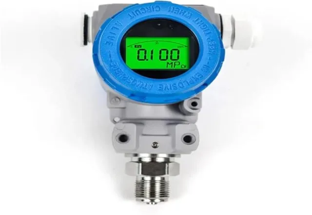
To understand calibration, it helps to separate the instrument’s stages:
- Sensor: converts pressure into an electrical signal that is digitized.
- Digital process variable (PV): the microprocessor calculates pressure in engineering units. This is the value read over HART.
- Scaling: the PV is compared with the lower and upper range values (LRV and URV) to calculate the percentage.
- Analog output: a digital-to-analog converter produces the 4–20 mA current that reaches the PLC or DCS.
The HART signal is a digital signal superimposed on the 4–20 mA current on the same pair of wires. For the communicator or calibrator to communicate, the loop needs a load resistance, typically around 250 Ω; the allowable value depends on the manufacturer and the power supply.
Calibrating, trimming and reranging are not the same
This is where the most common mistake happens. The operations a HART transmitter offers are different:
| Operation | What it does | Does it correct sensor error? |
|---|---|---|
| Rerange (LRV/URV) | Redefines which pressures correspond to 4 and 20 mA | No |
| Sensor trim | Corrects the digital reading against a reference pressure | Yes |
| Output trim (4 and 20 mA trim) | Corrects the digital-to-analog converter against a reference milliammeter | No; it corrects only the analog output |
If the sensor has an error and you only rerange with the communicator, the PV is still wrong and so is the current. Calibration, in the metrological sense, is comparing the instrument against a traceable reference standard and recording the errors. Adjustment is the correction made when those errors are out of tolerance.
What you need before you start
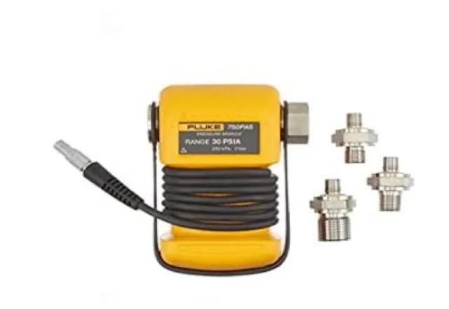
- Pressure source and reference: a hand pump or pressure generator and a reference module or gauge with a current calibration certificate.
- Current measurement: a milliammeter accurate enough to read the 4–20 mA output.
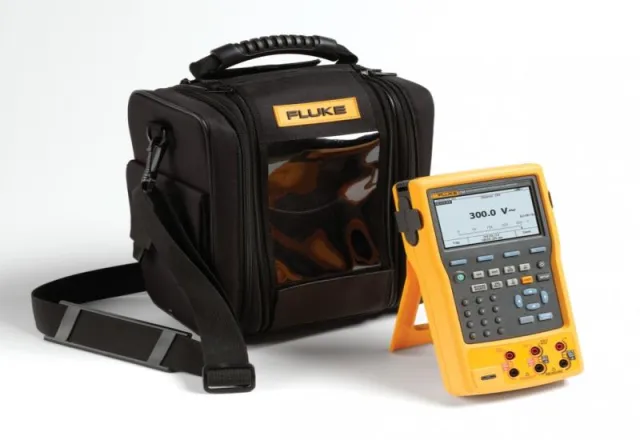
- HART communication: a field communicator or a documenting calibrator that combines pressure, mA measurement and HART in one unit.
- A defined tolerance: the maximum permissible error should come from the needs of the process, not just the transmitter datasheet.
- An adequate accuracy ratio: as a rule of thumb, the reference should be several times more accurate than the tolerance being checked; a 4:1 ratio is a common reference point. If that is not achievable, uncertainty must be taken into account when deciding whether the instrument passes.
You also need to coordinate with operations: put the loop in manual, notify the control room and confirm the transmitter is not part of a safety system that could trip during the test.
Step-by-step procedure
1. Isolate and connect
Isolate the transmitter from the process using the manifold or block valves, vent pressure safely and connect the pressure source and the reference. On differential pressure transmitters, use the equalizing valve according to the manifold procedure so the cell is not overpressured on one side.
2. Record the configuration
With the communicator, note the tag, units, LRV, URV, transfer function (linear or square root) and damping. If anything differs from the loop datasheet, check before changing it.
3. As-found test
Apply pressure at several points across the range, typically 0, 25, 50, 75 and 100%, first rising and then falling to see hysteresis. At each point record the applied pressure, the digital PV and the output current. Wait for the reading to settle before writing it down.
4. Calculate the error
Error is usually expressed as a percentage of span. For example, on a 0 to 10 bar range, the expected current at 50% is 12 mA; if you measure 12.08 mA, the error is 0.08 mA over a 16 mA span, or 0.5% of span. Compare the PV and the current separately: that tells you whether the problem is in the sensor, the output or both.
5. Adjust if needed
If it is out of tolerance, perform the sensor trim first (lower and upper, or whichever the manufacturer recommends), then the 4 and 20 mA output trim. If only the output is off, an output trim is enough.
6. As-left test
Repeat the full sequence of points and record the results. The certificate or record should include both tests, the identification and traceability of the reference standards, the ambient conditions and who performed the work.
Common mistakes that affect the result
- Liquid head: if the transmitter is mounted below or above the tap, or has liquid-filled impulse lines, the liquid column adds or subtracts pressure. Account for it when comparing with the process.
- Mounting position: some transmitters show a small zero shift depending on orientation. That is why the zero trim is done in the installed position.
- Leaks in hoses and fittings: a small leak means the reading never settles. Check before recording data.
- Temperature: compressing air in the pump changes its temperature, and the pressure drifts for a few seconds. Wait for it to stabilize.
- High damping: damping of several seconds slows the response and can lead you to record values too early.
Field or laboratory calibration
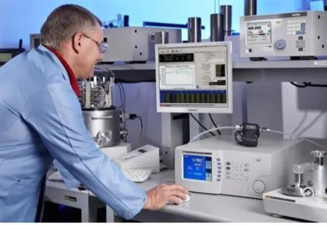
Field calibration avoids removing the instrument and lets you check the complete loop, including the PLC input card. Laboratory calibration offers controlled conditions and more accurate standards, and is preferable for reference instruments or when lower uncertainty is required. Many plants combine both: periodic on-site verification and formal laboratory calibration at longer intervals.
The calibration interval depends on criticality, the instrument’s stability history, the manufacturer’s recommendations and the requirements of your quality system. Reviewing the as-found results from several calibrations is the best basis for extending or shortening it.
How CreativeIT can help
At CreativeIT, an electrical and electronic testing laboratory in Monterrey, we offer HART pressure sensor calibration and laboratory calibration of pressure, temperature and HART signals, as well as calibration of gauges and transmitters. If your team prefers to calibrate on site, we also rent the Fluke 754 documenting calibrator. Contact us at (81) 4777 6921 or info@creativeit.mx to review your instruments.