An electrical installation can look flawless and still hide a loose protective conductor, insulation damaged while pulling cable, or a protective device that would not trip in time during a fault. Visual inspection is essential, but it is not enough: the only way to know that an installation protects people and equipment is to measure it. This guide explains which tests make up an electrical verification, the order in which to perform them, which standards support them (IEC 60364-6, the IEC 61557 series and NOM-001-SEDE in Mexico) and how to interpret the results without falling into the most common mistakes.
When should an installation be verified?
Verification is not a one-time formality. It makes sense at these points:
- Initial verification: before energizing a new installation, an extension or a newly built plant.
- After modifications: panel replacements, new circuits, relocated machinery or replaced feeders.
- Periodic verification: as part of preventive maintenance. The frequency depends on the type of installation, the environment (dust, humidity, vibration, corrosion) and internal or insurer requirements.
- After an incident: a short circuit, a fire, a flood or a lightning strike justifies checking the installation before returning to operation.
In Mexico, NOM-001-SEDE sets the safety requirements the installation must meet, and verification units (unidades de verificación) assess compliance where the law requires it. NOM-029-STPS, in turn, requires maintenance activities to be carried out under safe procedures and conditions. The tests described here are the technical tools to show that the installation complies.
The standards framework: IEC 60364-6 and IEC 61557
IEC 60364-6 describes what must be inspected and tested in a low-voltage installation. The IEC 61557 series defines the requirements for the instruments used in those tests, so that the measurements are reliable and safe. Each part covers one measurement:
| IEC 61557 part | Measurement |
|---|---|
| Part 2 | Insulation resistance |
| Part 3 | Loop impedance |
| Part 4 | Resistance of protective conductors and equipotential bonding (continuity) |
| Part 5 | Earth resistance |
| Part 6 | Residual current devices (RCDs) |
| Part 7 | Phase sequence |
A multifunction tester that declares compliance with IEC 61557 gives you confidence that the test current, voltage and accuracy are suitable for each measurement. An ordinary multimeter is not a substitute: for example, it cannot inject the current a continuity test requires or apply the voltage of an insulation test.
Visual inspection comes first
Before connecting any instrument, with the installation de-energized and locked out, check: conductor size and type, color coding, tightness of connections, condition of raceways, presence and physical continuity of the grounding conductor, panel labeling, protective devices suited to each circuit, working space in front of panels and the enclosure protection rating for the environment. Many faults are found here, before any measurement.
The tests, in the recommended order
Order matters. The first tests are done with the installation de-energized and confirm that it is safe to energize; the last ones require voltage.
1. Continuity of protective conductors
Measure the resistance between the panel ground bar and every point that must be grounded: receptacles, motor frames, metal piping, structures and equipotential bonds. IEC 61557-4 requires the instrument to inject at least 200 mA, with a low open-circuit voltage. A current like this reveals loose or corroded connections that a low-current measurement would miss.
There is no single universal limit: the acceptable value depends on the length and cross-section of the conductor and should be consistent with the calculated resistance. What matters is that there are no abnormal values between similar points. Before measuring, null the resistance of the test leads (the instrument’s “zero” function).
2. Insulation resistance
With circuits de-energized, a DC voltage is applied between live conductors and between them and ground. The test voltage and the minimum value depend on the circuit’s nominal voltage and on the edition of the standard; as a reference, IEC 60364-6 specifies 500 V DC for circuits up to 500 V, with a minimum of 1 MΩ. In a healthy installation the actual values are usually far above the minimum, so a result that “barely passes” deserves investigation.
Caution: disconnect or isolate sensitive electronics, drives, surge protectors and lamps with electronic ballasts before the test, or they may be damaged or distort the reading.
3. Polarity and phase sequence
Check that single-pole switches open the phase conductor (not the neutral), that receptacles are wired correctly and, in three-phase circuits, that the phase sequence is correct so motors turn in the expected direction.
4. Fault loop impedance
This test answers a key question: if a phase conductor touches a grounded enclosure, will enough current flow for the protective device to trip within the required time? The instrument measures the impedance of the loop formed by the source, the phase conductor and the protective conductor, and calculates the prospective fault current. That value is compared with the curve of the breaker or fuse protecting the circuit. A high impedance, caused by a long conductor or a poor connection, can make the protection too slow or prevent it from operating.
5. Residual current device testing
In many Mexican installations, following NOM-001-SEDE, personnel protection in wet locations is provided by ground-fault circuit interrupters (GFCIs, ICFT in Spanish) instead of the 30 mA RCDs common in IEC installations. In both cases the principle is the same: the device must open when the leakage current exceeds its threshold. The test verifies trip current and trip time. The device’s test button confirms the mechanism, but does not measure these values; for that you need a tester suited to the device type.
6. Earth electrode resistance
Finally, the resistance of the electrode or grounding grid is measured with an earth tester. The fall-of-potential method or clamp methods verify that the grounding system meets the value required by the applicable standard and by the design.
Common verification mistakes
- Not nulling the leads in the continuity test, which adds tenths of an ohm to every reading.
- Measuring insulation with equipment connected, giving false low values or damaging electronics.
- Relying only on the test button of residual current devices.
- Measuring loop impedance on a circuit with an RCD without using the instrument’s “no-trip” function, causing unnecessary trips.
- Not documenting: without a record of values per circuit there is no way to see trends at the next verification.
What the report should include
A good verification report identifies each panel and circuit, the instrument used with its current calibration certificate, the test conditions, the measured values against the acceptance criteria, and observations with prioritized corrective actions. This document is useful for audits, insurers and the maintenance team itself.
How CreativeIT can help
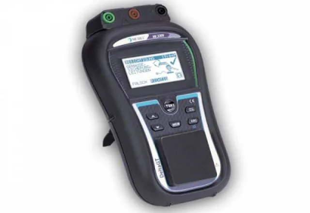
At CreativeIT Group we carry out electrical installation verification to IEC 60364, IEC 61557 and NOM-001-SEDE, and offer COMBI521 multifunction tester rental, sales of the Metrel MI3309 multifunction tester and insulation resistance testing of cables and windings. We help you plan the verification of your plant. Contact us at (81) 4777 6921 or info@creativeit.mx.