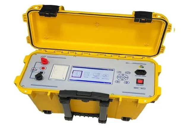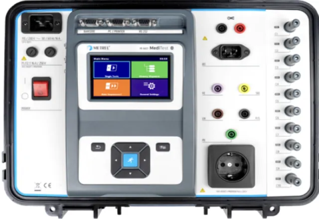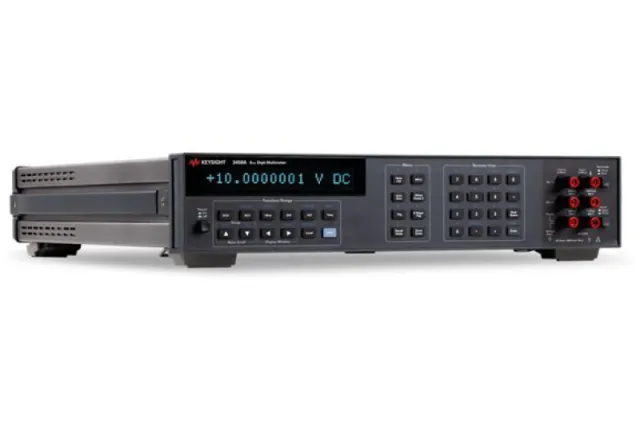
A connection that gains a few micro-ohms gives no sign at the panel, but it heats up every time load current flows through it. Worn breaker contacts, a poorly tightened bus joint or an oxidized lug can run for months before ending in a trip, an arc or an unplanned shutdown. Contact resistance testing, known on many plant floors as a “ductor” test, measures that defect directly with the equipment out of service. This guide explains how the test works, what current to use, how to make a reliable measurement and how to interpret the readings.
What the test measures and why it matters
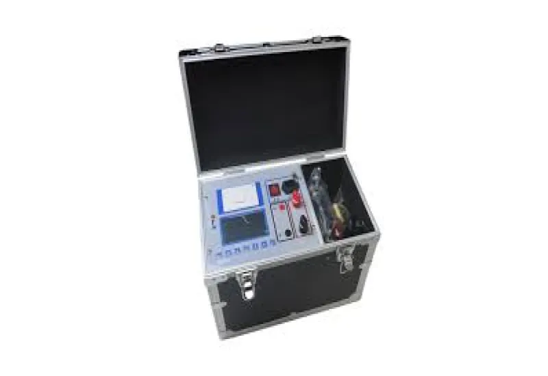
The test injects a known direct current through the contact or joint, measures the voltage drop across it and calculates resistance using Ohm’s law (R = V / I). Results are usually in micro-ohms (µΩ) or milliohms, depending on the equipment. The name “ductor” comes from a trade name that became generic; the instrument is properly called a micro-ohmmeter or low-resistance ohmmeter.
The practical importance lies in the power dissipated (P = I²R). At 1,000 A of load, a 100 µΩ joint dissipates about 100 W; if that joint degrades to 300 µΩ, it dissipates about 300 W in a very small spot. Heat speeds up oxidation, oxidation raises resistance, and the process feeds itself until the connection fails.
The test is mainly used on:
- Medium- and high-voltage power circuit breakers and disconnect switch contacts.
- Bolted bus joints in switchboards, MCCs and substations.
- Power cable terminations and splices.
- Grounding system connections and welded joints.
- Inter-cell connections in battery banks, following the manufacturer’s procedure.
Why you need a micro-ohmmeter
An ordinary multimeter won’t do this job. The resistance of its leads and probes is usually thousands of times higher than that of the contact, and its test current is very small. A micro-ohmmeter solves both problems:
- Four-wire (Kelvin) measurement: two leads inject the current and two separate leads measure the voltage. Because almost no current flows in the sense leads, their resistance doesn’t affect the reading.
- High current: it produces a measurable voltage drop (100 A through 50 µΩ gives 5 mV) and works the contact under conditions closer to real service, so thin oxide films don’t hide or exaggerate the result.
What test current to use
For high-voltage circuit breakers and switchgear, IEC 62271-1 calls for measuring main-circuit resistance with direct current between 50 A and rated current, and a 100 A minimum is often cited for ANSI/IEEE C37.09. That is why 100 A is a common choice in the field. Even so, the applicable criterion depends on the equipment and the edition of the standard: if the manufacturer specifies a current, follow it.
Portable test sets range from about 10 A to several hundred amperes. Low-current units can suit small joints and laboratory work, but on a power contact a very low current may give an unrepresentative reading. When comparing against historical results, always use the same current.
How to make a reliable measurement
Safety first
The test is done with the equipment de-energized, under lockout/tagout, and in line with site procedures, NOM-029-STPS-2011 (Mexico’s mandatory workplace standard for electrical maintenance) and the relevant risk assessment (NFPA 70E is the usual reference). In substations, also consider voltages induced by adjacent circuits. Never disconnect the current leads while the set is injecting, especially if there is inductance in the circuit.
Watch out for parallel paths
If a closed breaker has safety grounds on both sides, part of the current flows through that external path and the reading comes out lower than the true value. Site procedures should define how to handle this: remove one ground only if it is safe to do so, or use equipment and a method designed for measuring with both sides grounded. Never remove grounds just to make the measurement easier without that assessment.
Connecting the leads
- Clean the connection points: paint, grease or oxide under the clamp cause erratic readings.
- Place the current leads on the outside and the voltage leads on the inside, as close as possible to the contact being evaluated. Everything between the voltage points is part of the result.
- Always use the same measurement points so tests are comparable from year to year, and record them in the report.
- Wait for the reading to stabilize. Apply current only as long as needed, to avoid heating the joint.
- If the instrument allows it, measure in both polarities and average, especially at low currents, to reduce the effect of thermoelectric voltages.
On circuit breakers, follow the manufacturer’s instructions on operating the mechanism before measuring, and note in the report whether this was done, because a few operations can change the reading on a contact that has not moved for a long time.
How to interpret the results
There is no single acceptance value. Breaker readings are usually in the range of tens to hundreds of micro-ohms, but the limit depends on the design, the rated current and the section measured. The recommended order of references is:
- Manufacturer’s data: the primary criterion when it exists.
- Comparison between phases or similar joints: NETA specifications say to investigate values that deviate from adjacent poles or similar connections by more than 50% of the lowest value, when manufacturer’s data isn’t available.
- Historical trend: a sustained rise at the same point matters, even if the value is still within the limit.
A hypothetical example: a breaker reads 42, 45 and 118 µΩ on its three phases. Fifty percent of the lowest value is 21 µΩ, so the reference comes to 63 µΩ. The third phase exceeds it by a wide margin and should be investigated.
Temperature also has an effect. Copper’s resistance rises by about 0.39% per °C, so a 20 °C difference between two tests is equivalent to a change of roughly 8% in the metallic part of the circuit. Always record the temperature.
| What you see | Likely cause | What to do |
|---|---|---|
| One phase much higher | Worn contact, loose or oxidized joint | Inspect, correct per the manufacturer and retest |
| All three phases up against history | General wear, loss of contact pressure or changed measurement points | Check the test connections and inspect the mechanism |
| Unstable reading | Poorly placed clamp, dirty surface or poor contact | Clean, reconnect and repeat |
| Unexpectedly low reading | Parallel path or misplaced voltage leads | Check grounds and the section measured |
After any correction, repeat the test. If joints are retightened, use the specified torque: overtightening also damages a connection.
How it complements other tests
An infrared thermography survey is done with equipment energized and under load, and helps identify which connections to measure at the next shutdown. Contact resistance testing confirms the finding and leaves a numeric value you can compare. Neither replaces the other: the first covers many points quickly, and the second quantifies one at a time.
Frequently asked questions
Is a ductor the same as a megohmmeter?
No. A megohmmeter applies high voltage to measure very high insulation resistance, in megohms or gigohms. A micro-ohmmeter applies high current to measure very low resistance in conductors and contacts. They evaluate opposite things and complement each other.
How often should the test be done?
It depends on criticality, operating conditions and the manufacturer’s recommendations. It is usually included in the equipment’s scheduled maintenance, and also done after an intervention, a major fault or a thermographic finding.
How CreativeIT can help
CreativeIT, an electrical and electronic testing laboratory in Monterrey, performs ductor contact resistance testing and other electrical tests for industrial plants. If your team prefers to measure in-house, we also offer high-current micro-ohmmeter rental. Contact us at +52 (81) 4777 6921 or info@creativeit.mx to review your application.