Contact resistance (ductor) testing in Monterrey.
Applying NMX‑C‑407, ASTM E8, NMX‑B‑072 and ISO 15630‑1. We perform complete contact testing. All of our services adhere to international standards. We are active members of the IEEE and the DEIS (Dielectric and Electrical Insulation Society) # 94801861. We are your best option!!!
Recommendations for performing the test.
A) The equipment under test must be de-energized and in the closed position.
B) Electromagnetic induction should be isolated as much as possible, since it produces measurement errors and can damage the test equipment.
C) Thoroughly clean the connectors where the test equipment terminals will be placed with contact cleaner, so they do not affect the measurement, which is delicate.
What is contact resistance? Contact resistance is the resistance to current flow, due to surface conditions and other causes, when contacts touch each other (in the closed state of the device).
This can occur between the contacts of:
- Circuit breakers
- Contactors
- Relays
- Switches
- Connectors
Other switching devices.
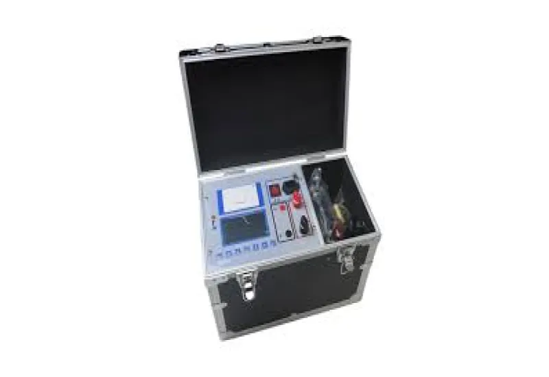
The contact resistance test, also known as the ductor test, measures the resistance of electrical connections: terminations, joints, connectors, busbar sections or cable connections, etc. These can be connections between any two conductors, for example cable connections or busbar sections. The instrument used to perform the ductor test is called an ohmmeter, and since its function is to perform the ductor test, the ohmmeter is also known as a ductor tester. The ductor tester comes in many variations, such as micro-, milli- and mega-ohmmeters, static resistance testers, or DLRO, which stands for Digital Low-Resistance Ohmmeter. It is used to measure resistance in different electrical testing applications. This tester consists of a DC ammeter and a few other components. The test measures resistance at the micro-ohm or milli-ohm level and is mainly used to verify that electrical connections are made correctly, and it can detect the following problems:
- Loose connections
- Proper tension in bolted joints
- Eroded contact surfaces
- Contaminated or corroded contacts
Contact resistance
The term contact resistance refers to the contribution to the total resistance of a system that can be attributed to the contact interfaces and electrical connections, as opposed to the intrinsic resistance, which is an inherent property independent of the measurement method. This effect is often described by the term Electrical Contact Resistance, or ECR, and it can vary over time, most often decreasing, in a process known as creep resistance. The idea of the potential drop at the injection electrode was introduced by William Shockley to explain the difference between experimental results and the gradual channel approximation model. In addition to the term ECR, “interface resistance,” “transition resistance,” or simply “correction term” are also used. The term “parasitic resistance” has been used as a more general term, where contact resistance is normally still assumed to make a major contribution.
Why do you need contact resistance testing? The contacts in a circuit breaker must be checked periodically to ensure the breaker is healthy and functional. Poorly maintained or damaged contacts can cause arcing, phase loss and even tripping. This test is especially important for contacts that carry large amounts of current (for example, busbars) because higher contact resistance can lead to lower current-carrying capacity and higher losses. The ductor test is generally performed using a micro/milli-ohmmeter or a low-resistance ohmmeter. Measuring contact resistance helps identify fretting corrosion of the contacts and makes it possible to diagnose and prevent it. An increase in contact resistance can cause a high voltage drop in the system, and that needs to be controlled.
Contact resistance is the contribution to the total resistance of a material due to imperfect contact at the interfaces between materials.
Typical cases are contact terminals and connections in electrical engineering, where an irregular contact can cause a different value to be measured than would be expected based on the materials and conductor length used. Contact resistance therefore depends on the measurement conditions, unlike intrinsic resistance, which is an inherent property of the material being measured. This resistance is studied and optimized, as in the case of switching devices and in measurements in the manufacture of electronic components.
Contact resistance depends on the state of wear of the terminals or test probe tips; the amount of oxide on the contact surfaces; the dirtiness of the surfaces; and the materials of the contact surfaces. Gold, silver and palladium are characterized by low contact resistance.
Measurement:
When placing the probes of an ohmmeter on the terminals of a 100-ohm resistor, a total resistance of 1 megohm, 1 kilohm or 101 ohms may be measured, depending on the accuracy or on how well the connection is made. Contact resistance is therefore the difference between the measured resistance and the true value of the resistance.