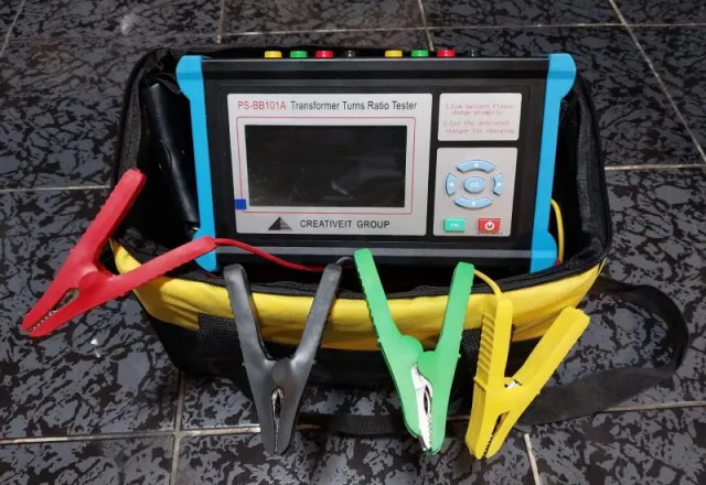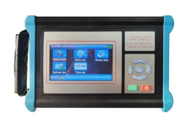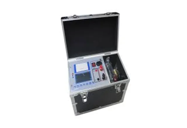
When a transformer trips on a fault, arrives new from the factory or comes back from a rewind, one of the first questions is whether its windings are still sound. The transformer turns ratio test, known as the TTR test, answers that question in minutes and at low voltage. It is simple to perform, but interpreting it correctly requires knowing the transformer’s connection, the tap changer position and the acceptance criteria that apply. This guide explains what the test measures, how it is done, how to read the results and which faults it can reveal.
What the TTR test measures
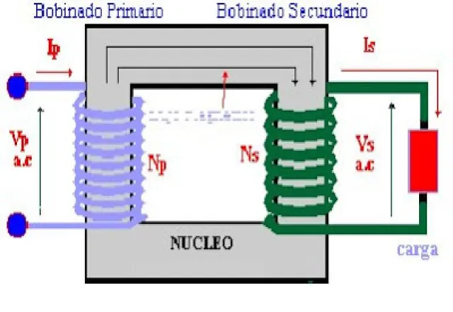
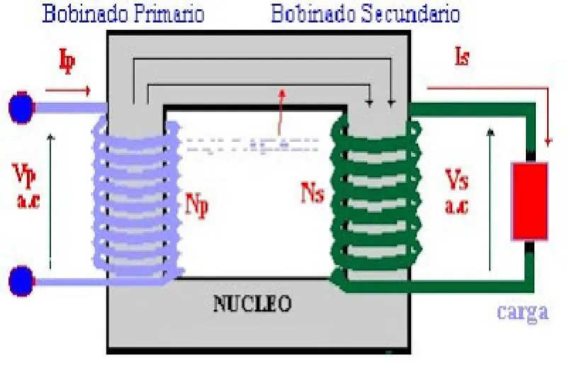
In an ideal transformer, the ratio between the high-voltage and low-voltage winding voltages equals the ratio of their numbers of turns. A TTR instrument applies a known AC voltage to one winding, measures the voltage induced in the other and calculates the ratio. That value is compared with the theoretical ratio derived from the nameplate for each tap.
Besides the ratio, most modern meters report:
- Percent deviation from the nameplate ratio.
- Excitation current drawn by the winding during the test.
- Phase deviation (angle) between the applied and induced voltages.
- Polarity and, on three-phase instruments, verification of the vector group (for example Dyn1 or Dyn11).
Because test voltages are low, the test does not stress the insulation; its purpose is to verify the integrity of the windings and magnetic circuit, not the condition of the insulation.
When to perform it
- Acceptance of a new or repaired transformer, to confirm it matches the nameplate and the factory test report.
- After a fault or protection operation (differential, Buchholz, overcurrent), before re-energizing.
- Periodic predictive maintenance, as part of the electrical test package along with insulation resistance, winding resistance and oil analysis.
- After changing the tap position or working on the tap changer contacts.
- When relocating a transformer, or when the nameplate is damaged or its connection is in doubt.
Standards and acceptance criteria
Test methods for liquid-immersed distribution and power transformers are described in IEEE C57.12.90, and the general requirements, including ratio tolerance, in IEEE C57.12.00. The most widely used criterion is that the no-load ratio must be within ±0.5% of the nameplate ratio. On the IEC side, IEC 60076-1 sets a similar tolerance for the principal tap, with additional conditions that depend on the transformer’s impedance and the tap. Dry-type transformers are covered by the standards of their own family (for example IEEE C57.12.91 for test methods).
Because standard editions change and some contracts or manufacturers specify their own criteria, always confirm which document and edition govern acceptance of the unit. Beyond the absolute limit, it is very useful to compare:
- The three phases against each other: they should give very similar results.
- Against the factory test report and previous tests on the same transformer.
- Against sister units of the same manufacturer and design.
How to perform the test, step by step
- De-energize and isolate the transformer, apply lockout/tagout (LOTO), verify absence of voltage and install temporary grounds in line with NOM-029-STPS and site procedures.
- Disconnect the high- and low-voltage cables or bus, so the instrument does not measure through connected loads, surge arresters or instrument transformers.
- Discharge the windings, especially if a DC insulation test was performed beforehand.
- Record the nameplate data: voltages, vector group, and the number and value of taps.
- Connect the leads as the instrument manual specifies: normally the H leads to the high-voltage winding and the X leads to the low-voltage winding. Reversing them can make the instrument excite the low-voltage winding and induce a high voltage on the high-voltage side, which is dangerous for people and for the instrument.
- Measure on every tap, phase by phase, noting the exact tap position for each reading.
- Remove the leads, discharge again and restore the connections before releasing the unit.
On three-phase delta-wye transformers, the per-phase ratio is not simply the quotient of the line voltages: a √3 factor comes in, depending on the vector group. Three-phase instruments do the calculation automatically if the vector group is set correctly; with single-phase instruments you must pick the right terminal pairs and correct the theoretical value.
How to interpret the results
| Observation | Possible cause |
|---|---|
| Ratio out of tolerance on one phase only, with high excitation current on that phase | Shorted turns in that phase’s winding. |
| No reading, or almost no induced voltage | Open winding, broken internal connection or loose terminal. |
| Error on some taps only | Worn or misaligned tap changer contacts, or a wrong internal connection on that tap. |
| All phases deviate by a similar amount | Wrong nameplate data, incorrectly recorded tap or wrong instrument setup. |
| Polarity or vector group differs from the nameplate | Incorrect internal or external connection; prevents parallel operation with other transformers. |
Excitation current deserves special attention. A shorted turn may change the ratio only slightly, yet it makes that phase’s excitation current rise noticeably. On three-legged core-type three-phase transformers it is normal for the center phase to draw less current than the outer phases; what is abnormal is a difference that breaks that pattern or changes from earlier tests. Keep in mind too that residual magnetism, for example after a DC winding resistance test, can alter the excitation current; that is why many guides recommend performing the TTR test before winding resistance, or demagnetizing the core.
Complementary tests
The TTR result is rarely interpreted on its own. A reliable transformer diagnosis combines:
- Winding resistance, which detects poor connections and high-resistance tap changer contacts.
- Insulation resistance and polarization index, to assess insulation between windings and to ground.
- Dielectric breakdown and oil analysis on liquid-filled units.
- Thermography in service, to find hot spots on connections and bushings.
Frequently asked questions
Can the TTR test damage the transformer?
No, provided it is done with the transformer de-energized and the leads connected correctly. Test voltages are low and do not stress the insulation. The real risk is reversed leads or working without verifying absence of voltage.
Can I use a multimeter and a power source to measure the ratio?
For a rough check it is possible, but the accuracy required (tenths of a percent) and the measurement of phase and excitation current make a TTR meter the right tool, especially when the result is used to accept or reject a unit.
Do I need a three-phase instrument?
A single-phase instrument works on any transformer, but on three-phase units with many taps a three-phase meter saves time and reduces connection errors.
How CreativeIT can help
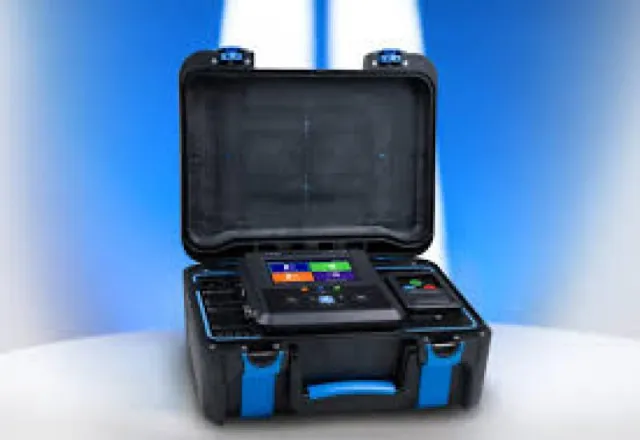
CreativeIT Group, an electrical and electronic test laboratory in Monterrey serving all of Mexico, performs transformer testing on site and in the lab, including turns ratio together with winding resistance and ducter testing. If your maintenance team prefers to run the tests, we offer TTR meter rental and portable turns ratio testers for sale. Our instruments are NIST-traceable and our engineers deliver a report that interprets the results. Contact us at +52 (81) 4777 6921 or info@creativeit.mx; we reply the same day.