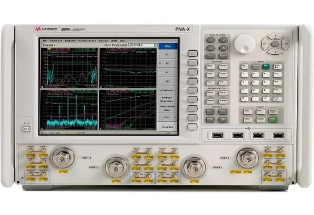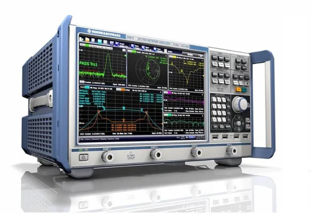
A vector network analyzer (VNA) can characterize an antenna, filter or amplifier with remarkable accuracy — and it can just as easily produce clean, convincing traces that are completely wrong. The difference is rarely the instrument itself. It is the calibration, the condition of the connectors and a clear understanding of what each S-parameter represents. This practical guide is for test, quality and design engineers working with RF in electronics, automotive and telecom plants.
S-parameters: the language of the VNA
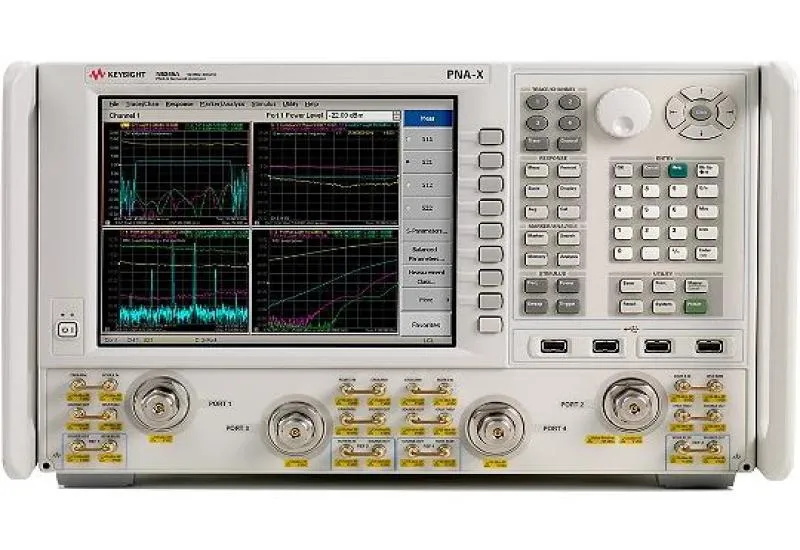
A VNA sends a known stimulus to the device under test (DUT) and measures, in both magnitude and phase, what is reflected and what is transmitted at each port. A two-port device gives four scattering parameters:
- S11 — input reflection (return loss, VSWR, input impedance).
- S21 — forward transmission (insertion loss, gain, group delay).
- S12 — reverse transmission (an amplifier’s reverse isolation).
- S22 — output reflection (output match).
The reported quantities follow directly from the reflection coefficient |Γ|: return loss = −20·log10|Γ| and VSWR = (1 + |Γ|) / (1 − |Γ|). A 2:1 VSWR is about 9.5 dB return loss; 1.5:1 is about 14 dB. Because the VNA measures phase, it can also show a Smith chart, group delay and — with the time-domain option — the location of discontinuities along a line.
Calibration: SOLT, TRL and electronic modules
An uncalibrated VNA measures the DUT together with the errors of its own cables, adapters and receivers: directivity, source and load match, reflection and transmission tracking, and isolation. A user calibration measures known standards and solves an error model — the 12-term model for a full two-port calibration — that the instrument then removes from every measurement. The result is that the reference plane moves to the end of the test cables, exactly where the DUT connects.
SOLT (Short-Open-Load-Thru)
The most common coaxial method. It uses a short, an open and a 50 Ω load on each port plus a direct thru between ports. Accuracy depends on how well the standards are defined, which is why every kit ships with a definition file (open and short coefficients, offset delays) that must match the physical kit loaded on the VNA.
TRL (Thru-Reflect-Line)
TRL uses a thru, a high-reflect standard that does not need to be known precisely, and one or more lines of known impedance. It is the preferred choice for test fixtures, PCBs and non-coaxial media, because the standards can be built in the same medium as the DUT. The trade-off is that each line covers a limited bandwidth, so wide frequency ranges need several lines.
Electronic calibration (ECal)
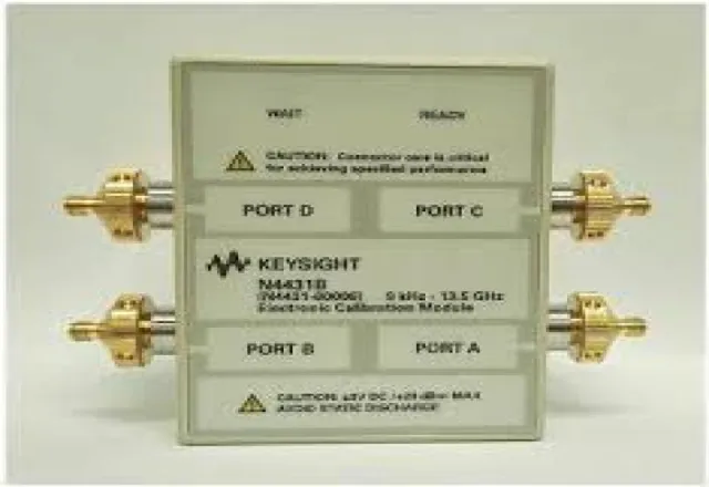
An electronic module contains switched impedance states characterized by the manufacturer. With one connection per port, the VNA runs a full calibration in seconds, reducing operator error and connector wear. It is ideal for production lines and labs with many setups — as long as the module’s characterization is current.
Why calibration kits and verification matter
A calibration is only as good as its standards. A kit with worn connectors, the wrong definition file or an out-of-date electronic module introduces systematic errors the VNA cannot detect on its own. Good practice:
- Send the VNA and its mechanical kit or ECal module out for periodic calibration with documented traceability — something ISO 9001, IATF 16949 and ISO/IEC 17025 auditors will ask for.
- Verify each user calibration by measuring a known device (an attenuator, an airline or a verification standard) before measuring the DUT.
- Gauge connectors: a center pin out of tolerance can damage the VNA’s test ports.
- Use a torque wrench. Commonly used values are 5 in-lb (0.56 N·m) for SMA, 8 in-lb (0.9 N·m) for 3.5 mm and 2.92 mm, and 12 in-lb (1.36 N·m) for Type-N; always confirm with the connector manufacturer.
- Do not move test cables after calibrating, and use phase-stable cables.
Typical applications
Antennas: return loss, VSWR and matching
S11 gives the resonant frequency, usable bandwidth and impedance. Calibrate at the antenna feed point or use port extension to remove the cable, and measure the antenna in its real environment: nearby metal, the enclosure or the user’s hand will shift resonance. The Smith chart is the tool for designing a matching network. Keep in mind that S11 tells you how much power gets into the antenna, not how much it radiates or in which direction — gain and pattern require a chamber or test range.
Cables and transmission lines
S21 gives insertion loss versus frequency and S11 shows mismatches. Time-domain mode pinpoints bad crimps, kinks or damage along the run.
Filters
S21 shows the passband, cutoff frequency and out-of-band rejection; S11 and S22 show the match. For high-rejection filters, narrow the IF bandwidth and add averaging to lower the noise floor.
Amplifiers
S21 is gain, S12 is reverse isolation and S11/S22 are the input and output match. Set port power low enough to keep the amplifier out of compression, and add attenuation at the output to protect the VNA receiver. A power sweep finds the 1 dB compression point.
Pre-measurement checklist
- Let the VNA warm up for the time the manufacturer specifies.
- Set frequency range, number of points, power and IF bandwidth before calibrating.
- Inspect, clean and gauge every connector.
- Load the correct kit definition, or use a current ECal module.
- Calibrate at the DUT reference plane and verify with a known device.
- Torque every connection and leave the cables still after calibration.
- Save the calibration state and record instrument, kit, date and conditions.
FAQ
What is the difference between a VNA and a cable and antenna analyzer?
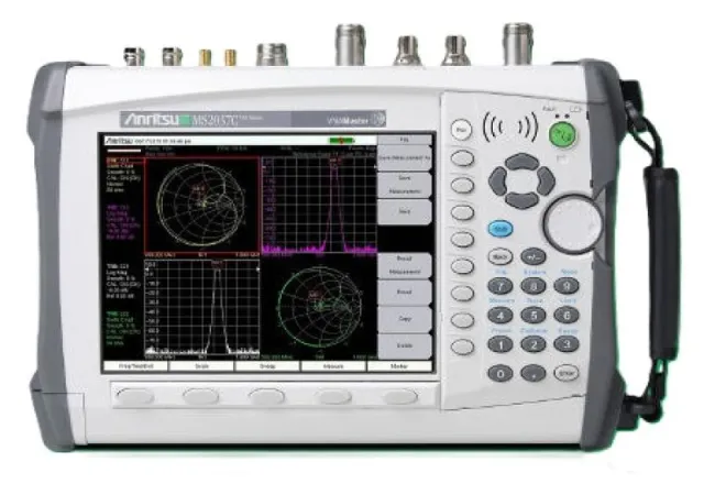
A cable and antenna analyzer is usually a handheld focused on S11, VSWR and distance-to-fault in the field. A VNA measures all four S-parameters with phase and higher dynamic range, so it is the tool for characterizing filters, amplifiers and components.
How often should I recalibrate on the bench?
Whenever the setup changes — frequency, power, cables or adapters — and whenever verification shows drift. Temperature changes and cable movement degrade a calibration over time.
Can I use another brand’s SOLT kit?
Yes, as long as you load that kit’s exact definition file into the VNA. With the wrong definition the calibration “completes” without complaint, but every measurement afterward is biased.
CreativeIT Group, a test and measurement laboratory in Monterrey serving all of Mexico, offers VNA rental up to 26.5 GHz, electronic calibration kit rental and VNA measurement services for antennas, cables, passives and amplifiers, documented with photos and video and using NIST-traceable instruments. If you are looking to buy, see our vector network analyzers for sale or rent. Our engineers reply the same day: contact us, call +52 (81) 4777 6921 or email info@creativeit.mx.