An OTDR (optical time-domain reflectometer) lets you see a fiber optic link end to end from a single end: it shows the length of the link, the loss of each splice and connector, and the location of a break or a tight bend. For maintenance staff in a plant, an industrial park or a telecom network, it is an essential tool. However, the trace it produces is not always easy to read, and a poor setup can hide real faults or show events that do not exist. This guide explains how it works, how to set it up and how to interpret what appears on screen.
How an OTDR works
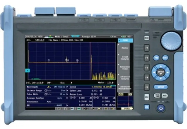
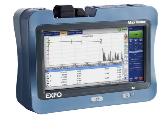
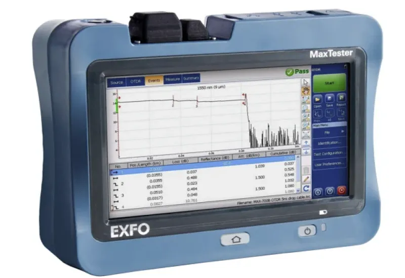
The OTDR sends short laser pulses down the fiber and measures the light that comes back. A small part of the light is scattered throughout the glass and returns toward the instrument (Rayleigh backscatter); in addition, connectors, mechanical splices and the end of the fiber produce reflections. By measuring the time each signal takes to return and knowing the refractive index of the glass, the instrument calculates the distance to each point. The result is a plot of power (dB) versus distance: the trace.
Parts of a trace
- Fiber slope. The descending line represents the attenuation of the glass, expressed in dB/km. Its value depends on the fiber type and the wavelength; in single-mode fiber it is lower at 1550 nm than at 1310 nm.
- Reflective events. Upward spikes followed by a step. They correspond to connectors, mechanical splices, clean breaks or the end of the fiber.
- Non-reflective events. Downward steps with no spike. They normally correspond to fusion splices or macrobends.
- End of fiber. A reflective spike followed by the signal dropping to the noise floor. If the fiber ends sooner than expected, that is where the break is.
Setup: the parameters that matter
Wavelength
Single-mode fiber is normally tested at 1310 and 1550 nm; multimode at 850 and 1300 nm. Testing at two wavelengths is very useful: a macrobend produces more loss at 1550 nm than at 1310 nm, while a splice usually shows similar loss at both.
Pulse width
This is the central trade-off of an OTDR. A short pulse gives better resolution and smaller dead zones, ideal for short links with many events, as in a plant. A long pulse carries more energy and reaches farther (greater dynamic range), but enlarges dead zones and can merge two nearby events into one. Many instruments have an automatic mode, but it is worth adjusting it manually to suit the link length.
Distance range and averaging time
Set the range to a value greater than the actual link length; if it is shorter, false events will appear. A longer averaging time reduces trace noise and improves the measurement of small events.
Index of refraction (IOR)
The distance the OTDR calculates depends on the configured refractive index. Use the value given by the cable manufacturer; an incorrect value shifts the location of every event, which matters a great deal when you need to locate a break in the field.
Dead zones and launch cables
After a strong reflective event, the OTDR’s detector saturates for an instant and cannot see what follows. That stretch is called a dead zone. There are two kinds:
- Event dead zone: the minimum distance needed to distinguish two consecutive reflective events.
- Attenuation dead zone: the minimum distance after an event before the loss of the next one can be measured.
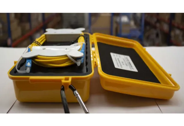
The first connector, the one joining the OTDR to the link, always falls inside the dead zone. That is why a launch cable is used: a known length of fiber between the instrument and the link, which allows the first connector to be characterized. To evaluate the last connector, another cable is placed at the far end (receive cable). The right length depends on the instrument and the pulse width; check the manufacturer’s recommendations.
Misleading events
Apparent gains (gainers)
Sometimes a splice appears to have gain, as if it amplified the signal. That is not possible: it happens when two fibers with different backscatter coefficients or mode field diameters are joined. In the opposite direction, the same splice will show an exaggerated loss. The solution is to measure in both directions and average; that is the true splice loss.
Ghosts
A very strong reflection can bounce back and forth in the fiber and appear as a false event at a multiple of the real event’s distance, often beyond the end of the fiber. If an event has no loss and appears at a suspicious distance, it is probably a ghost. Cleaning the connectors and reducing the pulse width usually helps.
Good practice
- Inspect and clean connectors before every connection. A dirty connector is the most common cause of bad measurements and can damage the OTDR port.
- Never connect the OTDR to a live fiber unless the instrument has a filtered port for that purpose. System light can damage the detector, and the OTDR pulse can disrupt service.
- Laser safety. Never look directly into a connector or fiber that may be live.
- Save the traces from installation as a baseline. Comparing them with future measurements is the fastest way to detect deterioration.
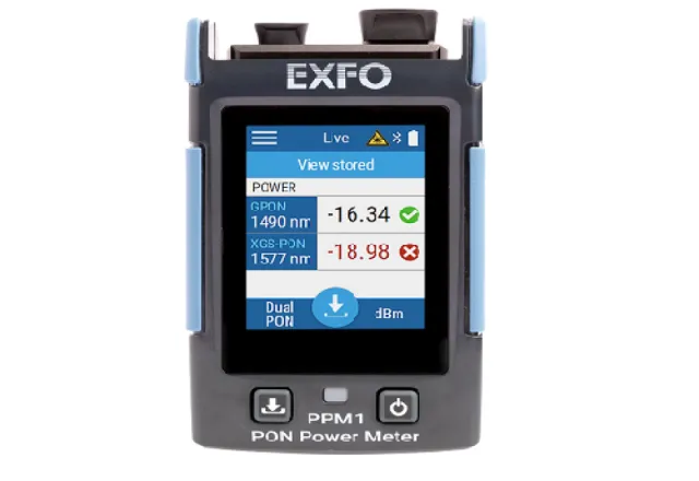
- Complement with optical power testing. Total link loss is best certified with a light source and an optical power meter; the OTDR shows where each loss is. Cabling standards such as TIA-568 or ISO/IEC 11801 set out how to calculate the acceptable loss budget.
Rent or buy
If your team installs or repairs fiber frequently, owning an OTDR saves response time. For a one-off fault location, project acceptance or an audit, renting is usually more practical. Either way, first define the fiber type, wavelengths, maximum link length and whether you need live-fiber testing.
How CreativeIT can help
At CreativeIT Group we offer OTDR rental and launch cables in Monterrey, and OTDR sales for fiber optics in Puebla. We help you choose the right setup for your network. Contact us at (81) 4777 6921 or info@creativeit.mx.