Temperature sensors are found in almost every industrial process: ovens, heat exchangers, tanks, molds, cold rooms and paint lines. An RTD or thermocouple that reads two degrees high can mean out-of-spec product, wasted energy or a nonconformity in an audit. The dry-well (dry-block calibrator) is the most widely used tool for checking and calibrating them on site or in the laboratory, but its result depends as much on technique as on the equipment. This guide explains how a dry-well works, how to perform a comparison calibration step by step, which sources of error to control and how to interpret the result.
What a dry-well is and how it works
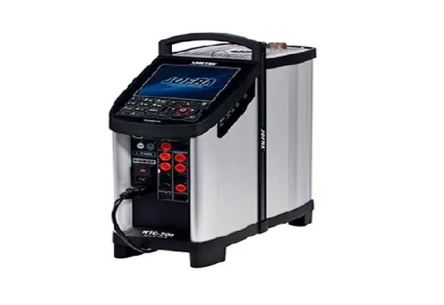
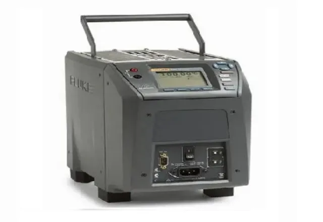
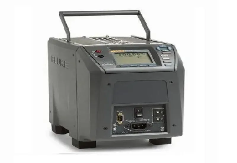
A dry-well is a heated (and in some models also cooled) metal block with one or more holes into which sensors are inserted. The instrument controls the block temperature and shows it on its display. Calibration is done by comparison: the sensor under test is placed in the block together with a more accurate reference and, once stable, their readings are compared. The reference can be:
- The dry-well’s internal control sensor: convenient, but accuracy is limited to the instrument’s display specification and to the difference between the zone of the internal sensor and the zone where the sensor under test sits.
- An external reference thermometer, typically a calibrated PRT (platinum resistance thermometer) with its readout. This is the preferred option when lower uncertainty is needed, because it measures in the same insert as the sensor under test.
Many dry-wells use interchangeable inserts with bores of different diameters. Using the right insert is an essential part of the calibration.
Specifications that matter
When choosing or evaluating a dry-well, display accuracy is only part of the picture. The EURAMET cg-13 guideline, which describes the calibration of temperature block calibrators, identifies the characteristics that contribute most to uncertainty:
- Stability: how much the block temperature varies over time once settled.
- Axial uniformity: the temperature difference along the depth of the bore. The bottom and the top of the block are not at the same temperature.
- Radial uniformity: the difference between bores in the same insert.
- Loading effect: the temperature change when several sensors or thick sensors are inserted, drawing heat from the block.
- Hysteresis: the difference between reaching a point while heating and while cooling.
The values depend on the model, the temperature range and the insert; check the data sheet and the dry-well’s own calibration certificate.
Immersion depth and insert fit
The most common cause of error is stem conduction: the sensor loses or gains heat to the outside through its sheath and head. To reduce it:
- Insert the sensor to the bottom of the bore. A widely quoted rule of thumb is an immersion of at least 15 times the sheath diameter plus the length of the sensing element; the real requirement depends on the sensor design and the temperature.
- Use a bore with the smallest possible clearance for the sensor diameter. Air is a poor conductor, and a large gap causes slower, offset readings.
- Run an immersion test: raise the sensor a few centimeters and watch whether the reading changes. If it changes significantly, immersion is not sufficient for that sensor.
- Place the reference and the sensor under test at the same depth, with their sensing elements at the same height.
Very short sensors, unusual shapes and surface sensors are not calibrated well in a standard dry-well; liquid baths, surface calibrators or dedicated fixtures are used for them.
Step-by-step calibration procedure
- Check the sensor. Inspect the sheath, cable and head. Measure the RTD resistance at room temperature or the thermocouple continuity and, where applicable, the insulation resistance between the element and the sheath.
- Define the test points. Choose three to five points covering the process operating range, with at least one near the normal operating point.
- Prepare the dry-well. Select the insert, clean it and set the unit up away from drafts and heat sources.
- Stabilize. Bring the block to the first point and wait until the temperature and the sensor reading are stable. The time depends on the dry-well, the range and the mass of the sensor.
- Record. Take several readings of the reference and the sensor under test over a defined interval and calculate the average and the error (sensor reading minus reference value).
- Repeat for each point. If you suspect hysteresis, run through the points both rising and falling.
- Document the “as found” results and, if adjusted, the “as left” results, together with the uncertainty and the traceability of the reference.
Calibrating the sensor alone or the whole loop
In the process, the sensor is almost always connected to a transmitter, controller or PLC. There are two approaches:
- Sensor-only calibration: its resistance or EMF is measured with a reference instrument. This characterizes the sensor and lets you reuse the result if the transmitter is replaced.
- Loop calibration: the sensor is placed in the dry-well and the temperature is compared with what the control system displays. It includes all the real errors: sensor, wiring, cold-junction compensation for thermocouples and transmitter scaling.
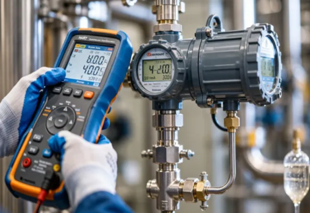
With smart transmitters, such as HART devices, the transmitter can be trimmed to compensate for the measured sensor error. That trim must be recorded and repeated if the sensor is replaced.
How to interpret the result
The error at each point is compared with the tolerance you need. For Pt100 RTDs, IEC 60751 defines tolerance classes; for example, class A is ±(0.15 + 0.002·|t|) °C and class B is ±(0.30 + 0.005·|t|) °C, where t is the temperature in °C. For thermocouples, IEC 60584 tolerances depend on the type and class. However, the process tolerance may be tighter or wider than the sensor manufacturer’s; what matters is whether the error, together with the calibration uncertainty, lets you meet what the process needs.
Good practice is for the calibration uncertainty to be several times smaller than the tolerance being checked. If they are close, a pass/fail decision is no longer reliable.
Common mistakes
- Taking readings before the block and the sensor have stabilized.
- Using an insert with oversized or dirty bores.
- Comparing against the dry-well display without considering its specification and uniformity.
- Using the wrong extension wire for thermocouples, or two-wire connections for RTDs, which add the lead resistance.
- Calibrating with a dry-well that does not have its own current, traceable calibration.
How CreativeIT can help
At CreativeIT Group we offer temperature sensor calibration with a dry-well and temperature and pressure sensor calibration with HART protocol, as well as dry-well rental so your team can check sensors on site. See also our laboratory calibration of pressure, temperature, flow and signals. Contact us at +52 (81) 4777 6921 or info@creativeit.mx with the sensor type and range you need to calibrate.