A PV installation can look flawless on the roof and still have a string with reversed polarity, a badly crimped connector or an insulation fault that will sooner or later trip the inverter on a ground fault. That is why commissioning does not end when the inverter shows power: it ends when every DC circuit has been tested and documented. The international reference for this is IEC 62446-1, which defines what documentation to hand over, what to inspect and which electrical tests to apply to grid-connected PV systems. This guide explains what it covers, how to interpret the results and what to watch for when testing.
What IEC 62446-1 covers
IEC 62446-1 (Requirements for testing, documentation and maintenance – Part 1: Grid connected systems) has three blocks:
- System documentation: general data, single-line diagram, module and inverter datasheets, mounting information, protection details and operation and maintenance information.
- Visual inspection: a review of the DC and AC sides, conductor selection and installation, protection devices, disconnects, earthing and labelling.
- Electrical tests: organised into two regimes, Category 1 and Category 2, plus additional tests where needed.
In Mexico, design and installation must also comply with NOM-001-SEDE, whose Article 690 covers solar photovoltaic systems. Depending on the type and size of the project and the interconnection conditions, an opinion from an electrical installation verification unit (UVIE) may be required. IEC 62446-1 does not replace those requirements, but it provides an orderly, recognised method to show the system was tested properly.
Category 1 tests
This is the minimum regime that applies to every system, regardless of size:
- AC circuit tests to IEC 60364-6 (or the equivalent local rules).
- Continuity of protective earthing and equipotential bonding conductors, including frames and structures where they are earthed.
- Polarity test of every string, before closing disconnects or inserting fuses.
- Combiner box test, to confirm each string is correctly connected in its position.
- Open-circuit voltage (Voc) of each string.
- Current of each string, short-circuit or operational.
- Functional tests of disconnects, inverters and protection.
- Insulation resistance of the DC circuits.
Category 2 and additional tests
Category 2 includes everything above and adds two very useful tests for medium and large systems:
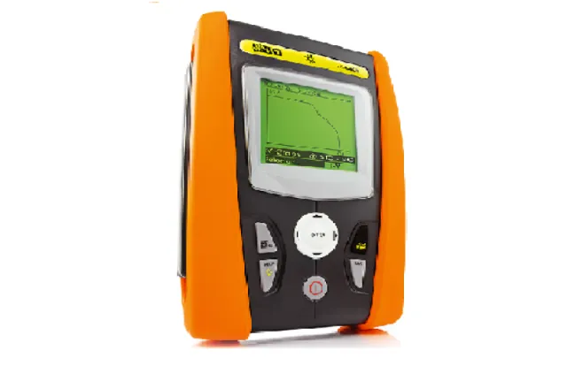
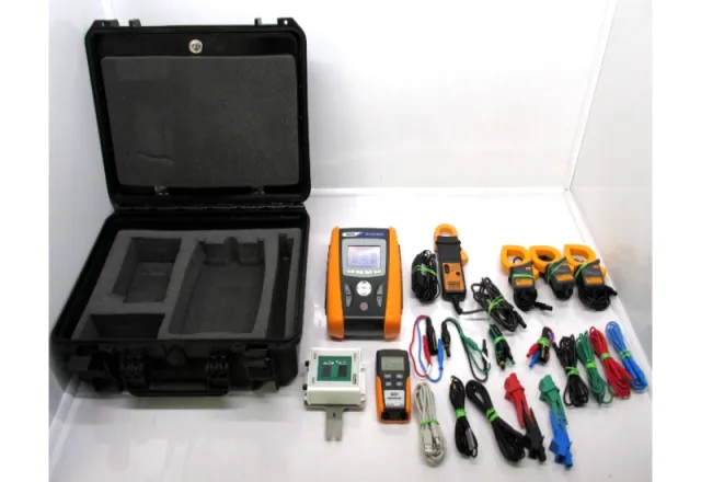
- I-V curve of each string, measured with a curve tracer plus irradiance and temperature sensors.
- Infrared inspection of modules and connections with a thermal camera.
Additional tests include voltage to ground on resistively earthed systems, blocking diode tests, wet insulation testing and shade evaluation. They are applied when the design or a suspected fault calls for them.
How to interpret each result
Polarity
A reversed string in a combiner box can damage fuses, diodes or the inverter itself when it is paralleled with the others. That is why this test is always done before energising. The result is simply right or wrong, but it should be recorded for every string.
Voc
The measured voltage is compared with the value expected from the datasheet, the number of modules in series and the cell temperature (Voc rises as temperature falls). Identical strings are also compared with each other: under stable irradiance they should agree very closely. A string with clearly lower voltage usually points to a missing module, a shorted bypass diode or a wiring error; a higher one may mean an extra module.
String current
Current depends directly on irradiance, so it only makes sense to compare it against the irradiance measured at the same moment, or between strings measured almost at the same time. Large differences point to shading, soiling, damaged modules or high-resistance connections.
Insulation resistance
It is measured between the DC conductors and earth, with the array disconnected from the inverter. The test voltage and the minimum acceptable value depend on the system voltage and are given in a table in the standard itself; use the edition that applies to your project. Beyond the minimum, compare strings with each other: one reading far below the rest deserves a look even if it “passes”. Morning humidity, dew and the array surface affect the reading, so record the conditions.
I-V curve
The measured curve is translated to standard test conditions (STC) using the irradiance and temperature data, then compared with the module model. Its shape reveals the type of problem:
| Curve shape | Likely cause |
|---|---|
| Steps or “knees” | Partial shading, module mismatch or bypass diodes conducting |
| Low current across the whole curve | Uniform soiling, degradation or an irradiance measurement error |
| Steep slope near Isc | Low shunt resistance, damaged cells |
| Shallow slope near Voc | High series resistance: connectors, cables or internal solder joints |
| Low Voc | Missing module, shorted diode or high cell temperature |
Thermography
Hot spots in cells, junction boxes or connectors only show clearly under sufficient, stable irradiance. Measurement conditions and anomaly classification are described in the technical specification IEC TS 62446-3. Thermography complements the I-V curve: one shows where the fault is, the other how much it affects performance.
Safety during testing
A PV array cannot be “switched off” in daylight: as long as there is light, the strings are live. Keep the following in mind:
- DC arcs do not self-extinguish the way AC arcs do. Never open connectors under load, and use a short-circuit switch designed for DC when the measurement requires it.
- Use instruments with a measurement category and DC voltage rating suited to the system (IEC 61010), and personal protective equipment according to the risk assessment.
- After the insulation test, discharge the circuits before handling them.
- Work under documented safety procedures, in line with NOM-029-STPS for maintenance of electrical installations.
When to repeat the tests
The same set of tests serves as a baseline. Repeating it periodically, after storms, hail, expansions or whenever monitoring shows lost production, lets you compare against the commissioning values and catch degradation before it becomes a failure. Keep the reports with the date, irradiance, temperature and instrument used.
How CreativeIT can help
At CreativeIT Group we carry out testing of PV systems and solar panels and verification of PV installations, with thermographic inspection of electrical panels as a complement. If you prefer your own staff to take the measurements, we also offer solar panel analyzer rental. Contact us at (81) 4777 6921 or info@creativeit.mx to plan the commissioning of your system.