When a line or switchboard is de-energized for maintenance, the hazard does not disappear the moment the breaker opens. Accidental re-energization, voltage induced from nearby circuits, lightning or energy stored in cables and capacitors can bring voltage back to the work location at any time. A temporary protective grounding set is the barrier that protects workers when that happens: it must carry the fault current long enough for the protection to operate and keep touch voltage low in the work zone. To do that, every assembly of clamps, cable and ferrules has to be correctly selected, correctly installed and in good condition. This guide explains how grounding sets are specified, how to inspect them before each use and what in-service testing to ASTM F2249 involves.
What temporary grounding is for
Temporary protective grounding does two jobs. First, it ties the phases together and to ground so that, if the circuit is re-energized, a bolted fault occurs and the protection operates as quickly as possible. Second, it creates an equipotential zone around the worker, so the voltage difference between what they touch and where they stand stays as low as possible while the fault lasts.
Mexico’s NOM-029-STPS includes the installation of temporary grounds among the measures for working on de-energized installations, together with a visible open point, lockout/tagout and verification of absence of voltage. NFPA 70E and, for substations, the IEEE 1246 guide describe the same principles. Grounding does not replace any of those steps: it is applied after confirming that no voltage is present.
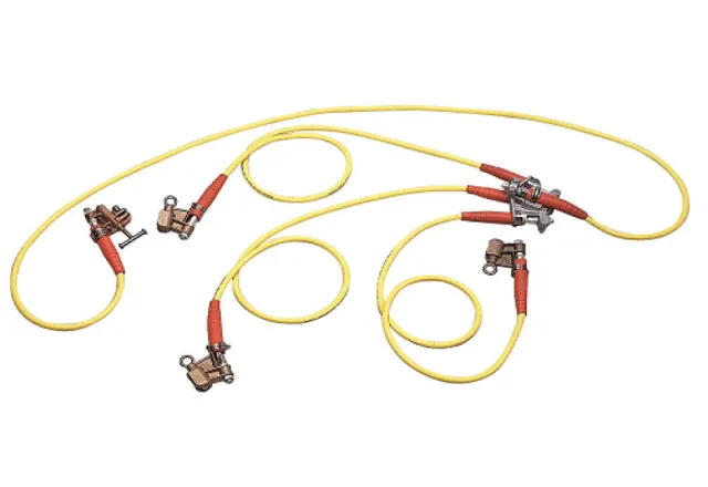
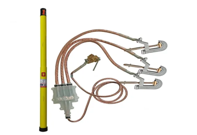
Components of a grounding set
- Clamps: attach to the phase conductor, the bus or the ground electrode. There are clamps for round conductors, flat bus and structures, tightened by hot stick or by hand depending on the design.
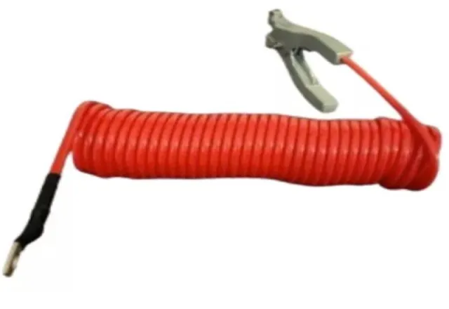
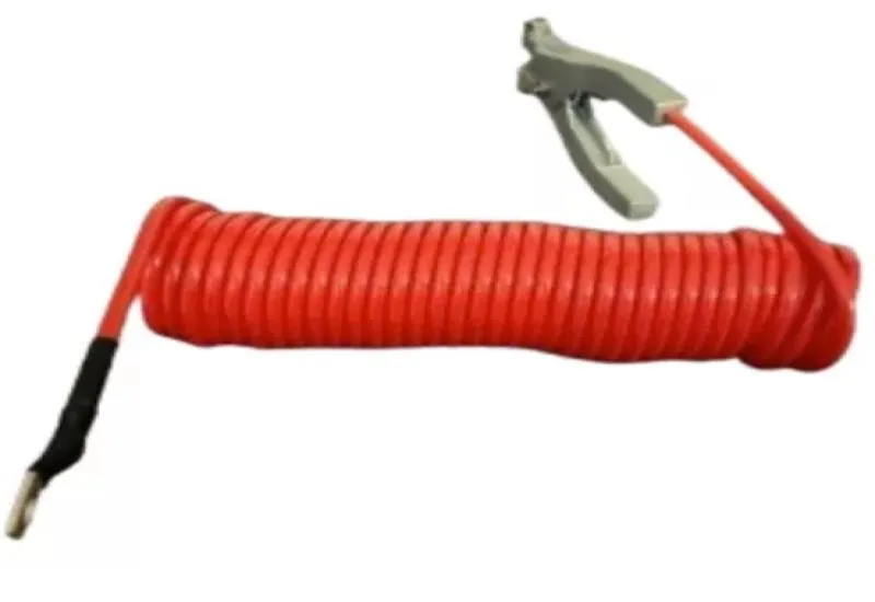
- Cable: extra-flexible copper with an insulating jacket. Many manufacturers use a clear or translucent jacket so broken strands, corrosion or heat damage can be seen.
- Ferrules: join the cable to the clamp. They are the most vulnerable point of the assembly, because flexing, corrosion and loosening concentrate there.
- Accessories: phase-to-phase jumpers or bonding heads, installation hot sticks and storage cases.
How sets are specified: ASTM F855
ASTM F855 is the reference specification for temporary protective grounding clamps, cables and ferrules. It classifies components into grades according to the symmetrical short-circuit current they can withstand for a given time, and defines the cable sizes associated with each grade. When choosing a set, what matters is:
- Knowing the available fault current where the set will be installed and the clearing time of the backup protection. These values come from the facility’s short-circuit study.
- Choosing a grade rated equal to or above that current for that time. The assembly is only as strong as its weakest component: a high-grade clamp on a lower-grade cable does not provide the clamp’s rating.
- Using the shortest practical cable length. Longer cable increases impedance, touch voltage in the work zone and the mechanical whipping forces during a fault.
- Checking that the clamps match the type and diameter of the conductor or bus they will be attached to.
The values for each grade depend on the edition of the standard; consult the current edition and the manufacturer’s data sheet rather than tables copied from another source.
Installation and removal: order matters
- Connect the ground end (bus or electrode) first, then the phase end with a hot stick. Remove in reverse order: phase first, ground last.
- Install the set as close to the work location as possible and, preferably, on both sides when voltage could come from either direction.
- Contact surfaces must be clean. Paint, corrosion and oxides raise connection resistance; some clamps have serrated jaws designed to bite through light layers.
- Lay out the cable with little slack and away from the worker, because electromagnetic forces during a fault can move it violently.
Inspection before each use
A visual check of a few minutes catches most problems:
- Clamps free of cracks and deformation, with threads and jaws in good condition and a mechanism that tightens firmly.
- Ferrules firmly attached to the cable, with no play, no green or white corrosion and no signs of overheating.
- Cable jacket free of cuts, crushing, bulges or hardened or discolored areas.
- No visibly broken strands, especially near the ferrules, where the cable flexes most.
A set that has carried fault current should be removed from service and evaluated before reuse: the forces and heating can damage clamps, ferrules and conductor even if it looks intact.
Periodic testing to ASTM F2249
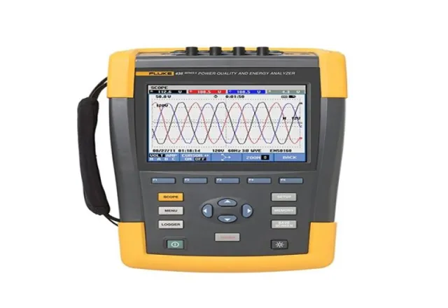
Many defects cannot be seen: broken strands inside the ferrule, internal corrosion or a crimp that has loosened with use. ASTM F2249 describes in-service test methods for temporary grounding jumper assemblies based on measuring the electrical resistance of the complete assembly, clamp to clamp, with a DC test current.
The principle is simple: the measured resistance is compared with the value expected for that cable size and length plus the contribution of the clamps and ferrules. A resistance above the acceptance criterion indicates a problem somewhere in the assembly. With equipment that measures continuously while the cable is flexed near the ferrules, intermittent connections can also be detected. Acceptance criteria and the exact procedure should be taken from the current edition of the standard and the manufacturer’s instructions.
There is no single test interval: it depends on how often the sets are used, the environment (humidity, salt, contamination) and the company’s safety policy. Good practice is to set the interval in writing, identify each set with a serial number and keep a record of every test and its result.
Common mistakes
- Using sets that are undersized for the facility’s fault current.
- Building or repairing sets in the shop with ferrules and tools other than the manufacturer’s.
- Connecting the phase clamp before the ground clamp, or removing the ground first.
- Leaving excess cable coiled or hanging near the worker.
- Storing sets loose in the back of a truck, exposed to impact, moisture and oil.
- Keeping no test records, which makes it impossible to show their condition during an audit or an incident investigation.
How CreativeIT can help
At CreativeIT Group we carry out conductivity testing of grounding clamps and sets to ASTM F2249 and testing of grounding clusters, and we offer grounding sets for sale. You can also browse the rest of our electrical services. Contact us at +52 (81) 4777 6921 or info@creativeit.mx with the number of sets and their cable sizes to schedule testing.