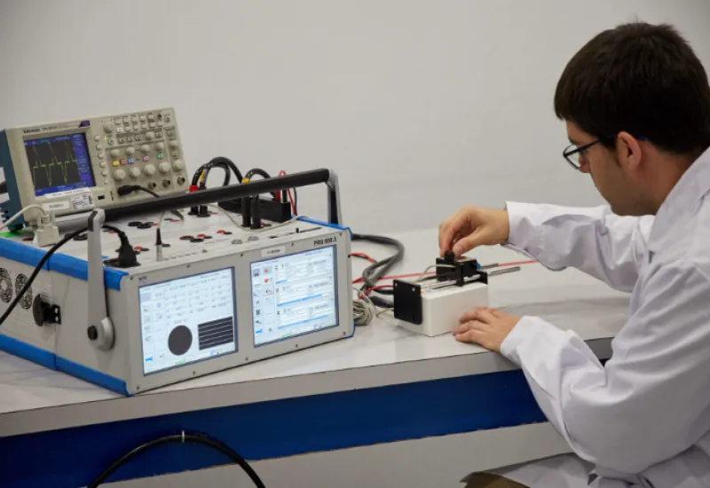
Radiated and conducted electromagnetic emissions are a natural physical consequence of any system in which current or voltage changes rapidly over time. In power electronics, DC-DC converters, inverters, PWM-controlled motors and switching power supplies, these effects arise from the principles established by Faraday’s Law and Lenz’s Law.
Understanding the physical origin of these emissions is essential for EMC testing, filter design, noise debugging and regulatory compliance validation.
Relationship Between Faraday’s Law, Lenz’s Law and EMC Emissions
Faraday’s Law states that a changing magnetic field induces an electromotive force in a nearby conductor.
V=-NdΦBdt
Where:
- V is the induced voltage
- N is the number of turns
- ΦB is the magnetic flux
- dΦBdtfrac{dPhi_B}{dt}dtdΦB represents the rate of change of the magnetic field over time
Lenz’s Law complements this phenomenon by stating that the induced current opposes the change that produced it. In practical terms, any fast current transition generates changing magnetic fields that induce unwanted currents and voltages in nearby traces, cables, shields and metal structures.
In EMC this translates into:
- Conducted emissions on power lines
- Radiated emissions from cables or PCBs
- Common-mode currents
- Inductive and capacitive coupling
- Interference between electronic modules
Why They Are Common in Switching Power Supplies and PWM Systems
Switching power supplies and PWM systems operate through fast ON/OFF transitions of MOSFET or IGBT transistors.
Each transition produces:
- High dV/dtdV/dtdV/dt values
- High dI/dtdI/dtdI/dt values
- High-frequency harmonics
- Transient electromagnetic fields
The faster the switching, the more spectral content appears at high frequencies.
For example:
|
System |
Typical switching frequency |
|
Flyback power supply |
20 kHz – 250 kHz |
|
Industrial buck converter |
100 kHz – 2 MHz |
|
Automotive inverter |
10 kHz – 50 kHz |
|
Motor PWM control |
2 kHz – 40 kHz |
|
Modern GaN converters |
1 MHz – 10 MHz |
Even if the fundamental frequency is in the hundreds of kHz, the harmonics generated can easily extend to:
- 30 MHz
- 100 MHz
- 500 MHz
- even several GHz due to extremely fast rise times
Typical Range of Conducted and Radiated Emissions
Conducted Emissions
Conducted emissions tests are normally evaluated over:
|
Typical EMC standard |
Range |
|
CISPR 11 |
150 kHz – 30 MHz |
|
CISPR 32 |
150 kHz – 30 MHz |
|
Automotive CISPR 25 |
150 kHz – 108 MHz |
These emissions travel mainly over:
- AC lines
- DC lines
- ground
- return paths
- shields
- harnesses
Radiated Emissions
Radiated emissions are usually measured over:
|
Application |
Common range |
|
Commercial/industrial |
30 MHz – 1 GHz |
|
Automotive |
up to 2.5 GHz |
|
Wireless electronics |
up to 6 GHz or more |
Long cables and PCB traces can behave as unintentional antennas when their electrical length matches fractions of a wavelength.
Practical Example: PWM Inverter for an Industrial Motor
A classic example is an industrial variable frequency drive that controls a three-phase motor using PWM.
Elements present:
- AC/DC rectifier stage
- Capacitor bank
- Power IGBTs or MOSFETs
- Gate drivers
- DSP or microcontroller
- Encoder
- Industrial communication
- Auxiliary SMPS
Frequent EMC problems:
- Common-mode current on ground
- Noise on the encoder
- Microcontroller resets
- False triggering of sensors
- Interference with industrial Ethernet
- Radiated emissions from the motor cable
In these systems, the motor cabling can act as a very long antenna because of the high voltage slew rates generated by the IGBTs.
Probe Orientation and Its Relationship to Electromagnetic Induction
EMC probes work precisely on Faraday’s Law: a changing magnetic flux induces a voltage in the probe’s internal coil.
Orientation is critical because the magnetic field has direction.
For Magnetic Fields (H-field)
The maximum reading occurs when:
- the plane of the probe loop is perpendicular to the magnetic flux
or equivalently:
- the probe axis is aligned with the field lines
For Currents in Conductors
Applying the right-hand rule:
- the magnetic field surrounds the conductor
- the probe must intercept those flux lines
In EMC debugging, this makes it possible to locate:
- current loops
- resonances
- high-radiation points
- switching nodes
Electronic Modules Normally Affected
In switching systems, it is common to find the following nearby:
- microcontrollers
- FPGAs
- DDR memories
- CAN/LIN buses
- industrial Ethernet
- analog sensors
- precision ADCs
- RF modules
- Bluetooth/WiFi
- LCD displays
- encoders
- USB interfaces
All of them can be vulnerable to electromagnetic interference.
Consequences of Not Performing EMC Testing
Skipping EMC testing can lead to:
- intermittent faults that are hard to diagnose
- random resets
- loss of communication
- data corruption
- measurement errors
- false protection trips
- regulatory non-compliance
- certification rejection
- product returns
- reputational damage
- higher redesign costs
In the automotive, medical, aerospace and industrial sectors, an EMC problem can pose critical functional risks.
Importance of Pre-Compliance Testing and EMC Debugging
Pre-compliance testing makes it possible to detect emissions problems before formal certification.
This reduces:
- design iterations
- validation time
- accredited laboratory costs
- risk of regulatory failure
Common tools used:
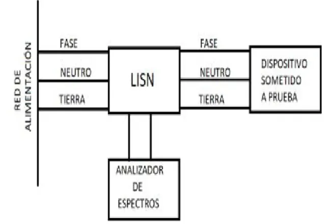
- LISN
- current probes
- near-field probes
- spectrum analyzers
- EMI receivers
- semi-anechoic chambers
- high-speed oscilloscopes
Correlating the underlying physics with EMC measurements is key to interpreting emissions correctly and applying effective solutions such as:
- EMI filtering
- layout control
- shielding
- ferrites
- return path control
- switching optimization
- current loop reduction
Typical Applications Where These Phenomena Are Studied
- Automotive electronics
- EV chargers
- Variable frequency drives
- DC-DC converters
- Industrial power supplies
- Medical equipment
- Railway systems
- Aerospace
- Consumer electronics
- Telecommunications
- Servers and data centers
- Industrial IoT equipment
Related EMC and Validation Services
Testing and analysis related to these phenomena typically include:
- conducted emissions
- radiated emissions
- EMC debugging
- near-field analysis
- pre-compliance validation
- EMI filter design
- common-mode current analysis
- switching power supply validation
- power integrity analysis
- testing of PWM inverters
- cabling and harness evaluation
- support for CISPR, IEC and automotive certification