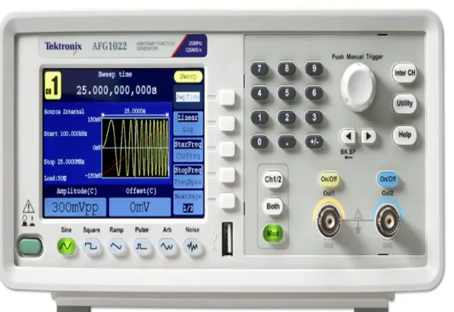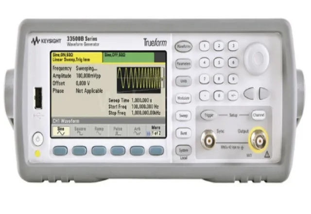
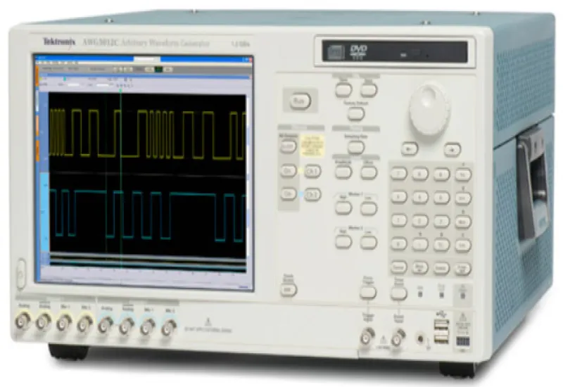
We have several types of one- and two-channel arbitrary waveform generators, up to 1 GS/s and up to 800 MHz.
Introduction
An acquisition instrument, usually an oscilloscope or a logic analyzer, is probably the first thing that comes to mind when you think about making electronic measurements. But these tools can only make a measurement when they can acquire a signal of some kind. And there are many cases in which such a signal is not available unless it is supplied externally.
A strain gauge amplifier, for example, does not produce signals; it simply increases the power of the signals it receives from a sensor. It inevitably becomes necessary to test the amplifier before connecting it to the circuit that feeds it. To use an acquisition instrument to measure the behavior of such devices, you must provide a stimulus signal at the input.
To cite another example, engineers must characterize their emerging designs to ensure that the new hardware meets design specifications across the full range of operating conditions and beyond. This is known as margin or limit testing. It is a measurement task that requires a complete solution, one that can both generate signals and make measurements.
The signal generator is combined with an acquisition instrument, such as an oscilloscope or a spectrum analyzer, to create a complete measurement solution. In its various configurations, the signal generator can provide stimulus signals in the form of analog waveforms, pulse patterns, modulation, intentional distortion, noise and more. To make effective design, characterization or troubleshooting measurements, it is important to consider both elements of the solution.
The arbitrary function generator (AFG) meets a wide range of stimulus needs; in fact, it is the predominant signal generator architecture in industry today. If the DUT requires the classic sine and square waveforms (to name a few) and the ability to switch almost instantly between two frequencies, the AFG is the right tool. An additional virtue is the low cost of the AFG, which makes it very attractive for applications that do not require the versatility of an arbitrary waveform generator (AWG).
Differential clock signals, e.g. for PECL, LVPECL or LVDS, can be generated with a dual-channel source with single-ended floating outputs.
To generate a differential signal, set the waveform, frequency and amplitude on Channel 1 and duplicate the inverted settings on Channel 2 through the CH1 Complement function in the quick settings menu. Then turn on sync mode by setting CH1=CH2 Frequency to On and starting Align Phase.
Disable any built-in clock source while driving the device with an external clock source.
To avoid degrading signal integrity, such as ringing or variable delay and amplitude, take care to obtain proper impedance matching between the probe that connects to the signal source and the board trace.