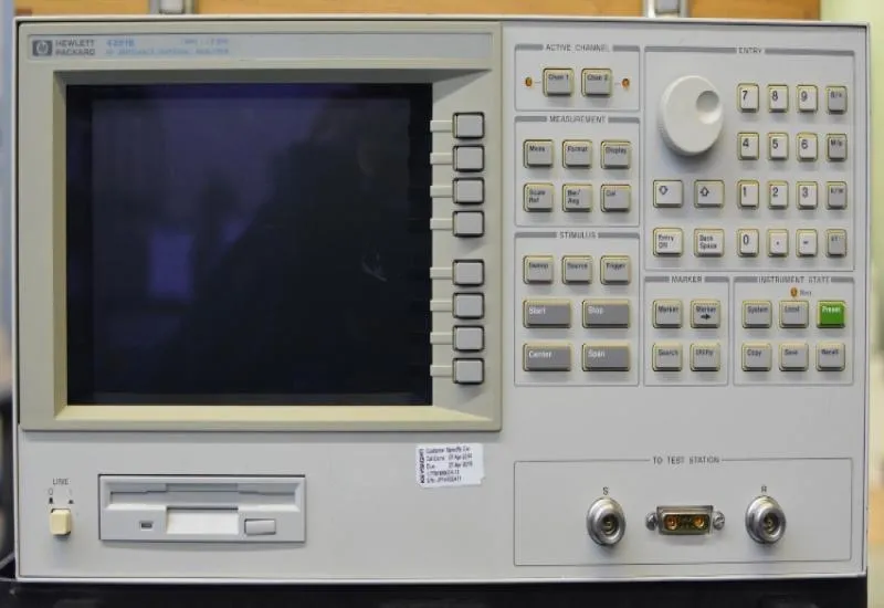
In RF, the difference between functional and exceptional lies in the measurement.
Are you certain that your measurements reflect the real behavior of your components at high frequency? When you work on RF applications, measuring in the right range lets you detect losses, variations and effects that do not appear in conventional tests, ensuring more stable and reliable designs.
The Agilent HP 4291B is an RF impedance analyzer from 1 MHz to 1.8 GHz, specialized in:
-
Complex impedance measurement (R + jX)
-
Measurement of L, C, R parameters
-
Quality factor (Q) analysis
-
Dielectric loss evaluation
-
Characterization of magnetic and ceramic materials
Unlike a conventional LCR analyzer, this instrument can work in the radio-frequency range, where electromagnetic phenomena become critical.
The Agilent HP 4291B is a fundamental tool for laboratories and engineering departments that need to meet measurement methods established by IEC standards applicable to high-frequency electronic components. Its ability to measure complex impedance up to 1.8 GHz makes it possible to perform accurate tests in the same range where many RF devices operate.
Among the most relevant standards is IEC 60384, which establishes specifications and test methods for fixed capacitors used in electronic equipment. This standard requires verifying parameters such as capacitance, dissipation factor (D), losses and frequency behavior. An RF impedance analyzer such as the 4291B can evaluate these parameters with high accuracy, especially in applications where performance at MHz or GHz is critical.
Another important standard is IEC 60289, related to measurement methods for high-frequency inductors and coils. For these devices it is essential to measure inductance (L), equivalent series resistance (ESR) and quality factor (Q) under real operating conditions. The instrument facilitates these measurements over a wide frequency range, making it possible to validate component performance against the established technical criteria.
IEC 60444-5 also stands out, which defines methods for measuring electrical parameters of quartz crystals using impedance and resonance analysis techniques. Thanks to its ability to analyze complex impedance and resonant behavior, the instrument can be used to characterize crystals and piezoelectric devices in high-frequency applications.
Key Technical Specifications
| Specification | Detail |
|---|---|
| Frequency Range | 1 MHz to 1.8 GHz |
| Frequency Resolution | 1 mHz |
| Measurement Parameters | |Z|, |Y|, θ, R, X, G, B, Cp, Cs, Lp, Ls, Rp, Rs, D, Q, Γ, and more |
| Basic Accuracy (Z) | ±0.8% |
| Impedance Range | 100 mΩ to 50 kΩ |
| Oscillator Level | 0.2 mV to 1 V (≤1 GHz) / 0.2 mV to 0.5 V (>1 GHz) |
| DC Bias | 0 V to ±40 V, 0 to ±100 mA |
-
High repeatability and stability
-
Advanced calibration system
Another lesser-mentioned advantage is its ability to be integrated into automated test systems (ATE) via GPIB, enabling repeatable, documented reports without constant manual intervention. This is key in high-volume electronics production lines.
Applications
-
Consumer Electronics and Telecommunications: Testing of SMD components (resistors, capacitors, inductors), RF filters, resonators and duplexers at their actual operating frequencies .
-
Semiconductor Characterization: Measurement of varactor diode and RF transistor parameters.
-
Advanced Materials Research:
-
Dielectric Materials: Evaluation of ceramic substrates, plastics and composites for the development of printed circuit boards and embedded passive components .
-
Magnetic Materials: Analysis of ferrites and other materials for the design of high-frequency inductors and transformers.
-
-
Temperature Testing (System Configuration):
-
Description of how to integrate the 4291B with a temperature chamber (e.g., Tabai Espec SU-240-Y) using the 1.8 m cable, the high-temperature heads and the IBASIC program to characterize components over a range of -30°C to +150°C .
-
Detailed Stages of the Measurement Process
1. Synthesized RF Signal Generation
The instrument incorporates a high-stability synthesized oscillator that produces a pure, controlled sine-wave signal.
Important characteristics:
-
Low harmonic distortion
-
High frequency stability
-
Precise amplitude control
-
Automatic sweep capability
This ensures that the measurement is not contaminated by internal variations.
2. RF Bridge-Type Measurement Network
This is where the critical part happens.
The 4291B uses an architecture based on a balanced measurement network (RF bridge method) designed to:
-
Minimize reflections
-
Reduce mismatch errors
-
Maintain controlled impedance across the entire range
The DUT is integrated into this network.
The system compares:
-
The incident signal
-
The resulting signal after interaction with the DUT
From this comparison it obtains the complex V/I ratio.
3. Separate Voltage and Current Sensing
At high frequency a simple shunt cannot be used as in DC.
The instrument uses:
-
High-speed internal sensors
-
Calibrated RF detectors
-
Directional signal separation techniques
Two fundamental signals are captured:
-
A component proportional to voltage
-
A component proportional to current
4. Vector Detection (Phase Measurement)
This is the heart of the system.
The instrument uses synchronous detection (similar to an RF lock-in) to determine:
-
Phase difference with very fine resolution
-
In-phase components (I)
-
Quadrature components (Q)
This yields:
-
The real (resistive) part
-
The imaginary (reactive) part
Without phase measurement it would not be possible to distinguish between capacitive and inductive behavior.
5. Internal Mathematical Conversion
Once the vector components are obtained, the internal processor automatically calculates:
-
R (series or parallel resistance)
-
X (reactance)
-
Ls / Lp
-
Cs / Cp
-
Q (quality factor)
-
D (dissipation factor)
-
|Z| and angle θ
All of this in real time during the frequency sweep.
6. Error Correction (OPEN / SHORT / LOAD Calibration)
To ensure accuracy in RF, the system applies compensations through:
-
Open-circuit calibration
-
Short-circuit calibration
-
Known standard load
These routines correct:
-
Systematic errors
-
Fixture parasitics
-
Mismatches
-
Phase errors
Without this step, measurement at GHz would be inaccurate. Why would it be inaccurate?
Because in that range:
-
Cables behave as transmission lines
-
Reflections appear
-
Phase shift becomes critical
-
Parasitics dominate the behavior
In projects where every electrical parameter influences the final result, having the right instrumentation is not a luxury; it is an investment in technical reliability.
Need Advice or a Quote?
Contact us today on WhatsApp at 8117860768 for pricing, availability and usage recommendations. At Creativeit Group, our specialized technical team can help you integrate it into your measurement processes.